
Users Guide
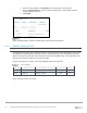
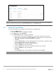

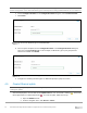

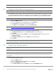
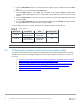
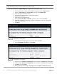
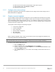
Table Of Contents
- 1 Introduction
- 2 SmartFabric Services for PowerEdge MX: An overview
- 3 SmartFabric mode requirements, guidelines, and restrictions
- 3.1 Create multi-chassis management group
- 3.2 Upstream network requirements
- 3.3 VLAN scaling guidelines
- 3.4 Configuring port speed and breakout
- 3.5 Switch slot placement for SmartFabric mode
- 3.6 Switch-to-Switch cabling
- 3.7 NIC teaming guidelines
- 3.8 Maximum Transmission Unit (MTU) behavior
- 3.9 Other restrictions and guidelines
- 4 Creating a SmartFabric
- 4.1 Physically cable MX chassis and upstream switches
- 4.2 Define VLANs
- 4.3 Create the SmartFabric
- 4.4 Configure uplink port speed or breakout, if needed
- 4.5 Create Ethernet uplink
- 4.6 Configure Fibre Channel universal ports
- 4.7 Create Fibre Channel uplinks
- 4.8 Configuring the upstream switch and connect uplink cables
- 5 Deploying a server
- 6 SmartFabric operations
- 7 Switch operations
- 8 Validating the SmartFabric deployment
- 9 SmartFabric troubleshooting
- 9.1 Troubleshooting errors encountered for port group breakout
- 9.2 Troubleshooting Spanning Tree Protocol (STP)
- 9.3 Verify VLT/vPC configuration on upstream switches
- 9.4 Discovery of FEM and compute sleds
- 9.5 Troubleshooting uplink errors
- 9.6 Troubleshooting FC/FCoE
- 9.7 SmartFabric Services – Troubleshooting commands
- 10 Uplink configuration scenarios
- 10.1 Scenario 1 - SmartFabric deployment with Dell EMC PowerSwitch Z9100-ON upstream switches
- 10.2 Scenario 2 - SmartFabric connected to Cisco Nexus 3232C switches
- 10.3 Scenario 3: Connect MX9116n FSE to Fibre Channel storage - NPIV Proxy Gateway mode
- 10.4 Scenario 4: Connect MX9116n FSE to Fibre Channel storage - FC Direct Attach
- 10.5 Scenario 5: Connect MX5108n to Fibre Channel storage - FSB
- 10.6 Scenario 6: Configure Boot from SAN
- A Hardware used in this document
- B Dell EMC Unity information
- C Additional information
- D Validated components
- E Technical resources
- F Support and feedback
39 Dell EMC PowerEdge MX SmartFabric Configuration and Troubleshooting Guide
Note: This is only done on CNA ports that carry converged traffic. In this example, these are the two 25GbE
QLogic CNA ports on each server that attach to the fabric internally.
If the system is already in System Setup from the previous section, skip to step 4.
1. Using a web browser, connect to the iDRAC server and launch the Virtual Console.
2. From the Virtual Console, click Next Boot menu then select BIOS Setup.
3. Select the option to reboot the server.
4. On the System Setup Main Menu, select Device Settings.
5. Select the first CNA port.
6. Select Device Level Configuration.
7. Set the Virtualization Mode to NPAR, if not already set, and then click Back.
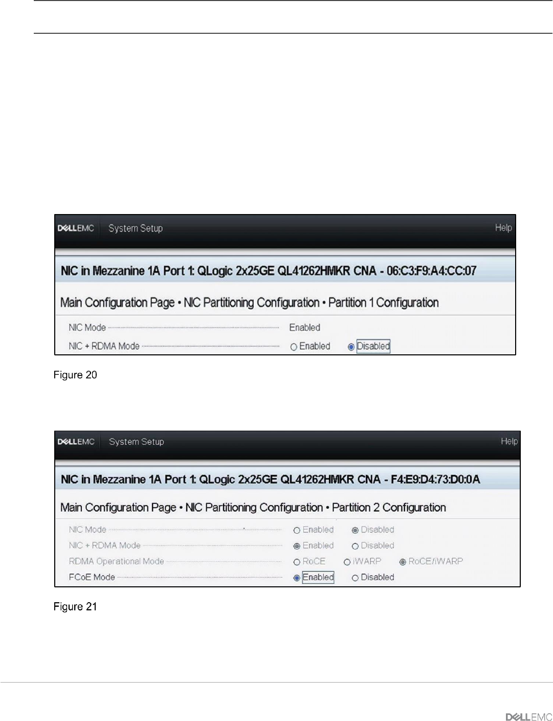
8. Select NIC Partitioning Configuration, Partition 1 Configuration, and click to set the NIC +
RDMA Mode to Disabled.
9. Click Back.
CNA partition 1 configuration
10. Select Partition 2 Configuration and set the NIC Mode to Disabled.
11. Set the FCoE Mode to Enabled, then click Back.
CNA partition 2 configuration
12. If present, select Partition 3 Configuration and set all modes to Disabled, then click Back.
13. If present, select Partition 4 Configuration and set all modes to Disabled, then click Back.
14. Click Back, and then Finish.
15. When prompted to save changes, click Yes and then click OK in the Success window.