
Users Guide
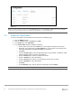

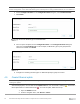

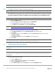
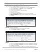
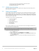
Table Of Contents
- 1 Introduction
- 2 SmartFabric Services for PowerEdge MX: An overview
- 3 SmartFabric mode requirements, guidelines, and restrictions
- 3.1 Create multi-chassis management group
- 3.2 Upstream network requirements
- 3.3 VLAN scaling guidelines
- 3.4 Configuring port speed and breakout
- 3.5 Switch slot placement for SmartFabric mode
- 3.6 Switch-to-Switch cabling
- 3.7 NIC teaming guidelines
- 3.8 Maximum Transmission Unit (MTU) behavior
- 3.9 Other restrictions and guidelines
- 4 Creating a SmartFabric
- 4.1 Physically cable MX chassis and upstream switches
- 4.2 Define VLANs
- 4.3 Create the SmartFabric
- 4.4 Configure uplink port speed or breakout, if needed
- 4.5 Create Ethernet uplink
- 4.6 Configure Fibre Channel universal ports
- 4.7 Create Fibre Channel uplinks
- 4.8 Configuring the upstream switch and connect uplink cables
- 5 Deploying a server
- 6 SmartFabric operations
- 7 Switch operations
- 8 Validating the SmartFabric deployment
- 9 SmartFabric troubleshooting
- 9.1 Troubleshooting errors encountered for port group breakout
- 9.2 Troubleshooting Spanning Tree Protocol (STP)
- 9.3 Verify VLT/vPC configuration on upstream switches
- 9.4 Discovery of FEM and compute sleds
- 9.5 Troubleshooting uplink errors
- 9.6 Troubleshooting FC/FCoE
- 9.7 SmartFabric Services – Troubleshooting commands
- 10 Uplink configuration scenarios
- 10.1 Scenario 1 - SmartFabric deployment with Dell EMC PowerSwitch Z9100-ON upstream switches
- 10.2 Scenario 2 - SmartFabric connected to Cisco Nexus 3232C switches
- 10.3 Scenario 3: Connect MX9116n FSE to Fibre Channel storage - NPIV Proxy Gateway mode
- 10.4 Scenario 4: Connect MX9116n FSE to Fibre Channel storage - FC Direct Attach
- 10.5 Scenario 5: Connect MX5108n to Fibre Channel storage - FSB
- 10.6 Scenario 6: Configure Boot from SAN
- A Hardware used in this document
- B Dell EMC Unity information
- C Additional information
- D Validated components
- E Technical resources
- F Support and feedback

38 Dell EMC PowerEdge MX SmartFabric Configuration and Troubleshooting Guide
5 Deploying a server
Before beginning, ensure that all server firmware, especially the NIC/CNA, has been updated to the latest
version.
5.1 Server preparation
The examples in this guide use a reference server of a Dell EMC PowerEdge MX740c compute sled with
QLogic (model QL41262HMKR) Converged Network Adapters (CNAs) installed. CNAs are required to
achieve FCoE connectivity. Use the steps below to prepare each CNA by setting them to factory defaults (if
required) and configuring NIC partitioning (NPAR) if needed. Not every implementation requires NPAR.
Note: iDRAC steps in this section may vary depending on hardware, software and browser versions used. See
the Installation and Service Manual for your PowerEdge server for instructions on connecting to the iDRAC.
From the link, select your server, then Manuals and documents.
5.1.1 Reset server CNAs to factory defaults (if required)
Note: If you are running the 14.10.xx firmware version, you must first update the firmware version to the newest
release.Because when a Qlogic QL41262 is reset to default, and incorrect value for Energy Efficient Ethernet
(EEE) is set to "Balanced" mode. The correct value for this should be "Disabled", and this is set correctly at
factory. This only occurs on 14.10.xx firmware.
The results of this setting causes the FCOE link not to establish even after the reboots.
To avoid this, you can extract Winfwnx2.exe, Tcl85.dll, QLMAPla.dll files from Windows Firmware DUP, and
change the Energy Efficient Ethernet parameter from 1 to 0.
To achieve that use the utility to run the following commands:
cfg -show eee_power_mode to show EEE mode.
cfg -eee_power_mode 0 to change the mode.
This will resolve the issue.
Reset the CNAs to their factory defaults using the steps in this section. Resetting CNAs to factory default is
only necessary if the CNAs installed have been modified from their factory default settings.
1. From the OME-M console, select the server to use to access the storage.
2. Launch the server Virtual Console.
3. From the Virtual Console, select Next Boot then BIOS Setup.
4. Reboot the server.
5. From the System Setup Main Menu, select Device Settings.
6. From the Device Settings page, select the first CNA port.
7. From the Main Configuration page, click the Default button.
8. Click Yes to load the default settings, and then click OK.
9. Click Finish. Notice if a message indicates a reboot is required for changes to take effect.
10. Click Yes to save changes, then click OK.
11. Repeat the steps in this section for each CNA port listed on the Device Settings page.
If required per step 9, reboot the system and return to System Setup to configure NIC partitioning.
5.1.2 Configure NIC partitioning on CNAs
In this example, each QLogic CNA port is partitioned into one Ethernet and one FCoE partition.