
Users Guide
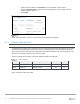
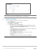

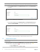

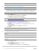
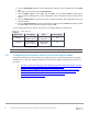
Table Of Contents
- 1 Introduction
- 2 SmartFabric Services for PowerEdge MX: An overview
- 3 SmartFabric mode requirements, guidelines, and restrictions
- 3.1 Create multi-chassis management group
- 3.2 Upstream network requirements
- 3.3 VLAN scaling guidelines
- 3.4 Configuring port speed and breakout
- 3.5 Switch slot placement for SmartFabric mode
- 3.6 Switch-to-Switch cabling
- 3.7 NIC teaming guidelines
- 3.8 Maximum Transmission Unit (MTU) behavior
- 3.9 Other restrictions and guidelines
- 4 Creating a SmartFabric
- 4.1 Physically cable MX chassis and upstream switches
- 4.2 Define VLANs
- 4.3 Create the SmartFabric
- 4.4 Configure uplink port speed or breakout, if needed
- 4.5 Create Ethernet uplink
- 4.6 Configure Fibre Channel universal ports
- 4.7 Create Fibre Channel uplinks
- 4.8 Configuring the upstream switch and connect uplink cables
- 5 Deploying a server
- 6 SmartFabric operations
- 7 Switch operations
- 8 Validating the SmartFabric deployment
- 9 SmartFabric troubleshooting
- 9.1 Troubleshooting errors encountered for port group breakout
- 9.2 Troubleshooting Spanning Tree Protocol (STP)
- 9.3 Verify VLT/vPC configuration on upstream switches
- 9.4 Discovery of FEM and compute sleds
- 9.5 Troubleshooting uplink errors
- 9.6 Troubleshooting FC/FCoE
- 9.7 SmartFabric Services – Troubleshooting commands
- 10 Uplink configuration scenarios
- 10.1 Scenario 1 - SmartFabric deployment with Dell EMC PowerSwitch Z9100-ON upstream switches
- 10.2 Scenario 2 - SmartFabric connected to Cisco Nexus 3232C switches
- 10.3 Scenario 3: Connect MX9116n FSE to Fibre Channel storage - NPIV Proxy Gateway mode
- 10.4 Scenario 4: Connect MX9116n FSE to Fibre Channel storage - FC Direct Attach
- 10.5 Scenario 5: Connect MX5108n to Fibre Channel storage - FSB
- 10.6 Scenario 6: Configure Boot from SAN
- A Hardware used in this document
- B Dell EMC Unity information
- C Additional information
- D Validated components
- E Technical resources
- F Support and feedback
37 Dell EMC PowerEdge MX SmartFabric Configuration and Troubleshooting Guide
5. From the Add Uplinks window, use the information in Table 8 to enter an uplink name in the Name
box.
6. Optionally, enter a description in the Description box.
7. From the Uplink Type list, select Type, then click Next. In this example, FCoE as Uplink type is
selected. Choose Uplink type as per your configuration from FC Gateway, FC Direct Attach or FCoE
options.
8. From the Switch Ports list, select the FC ports as defined in Table 8. Select appropriate port for the
connected uplink.
9. From the Tagged Networks list, select VLAN defined in Table 8, then click Finish. SmartFabric creates
the uplink object and the status for the fabric changes to OK.
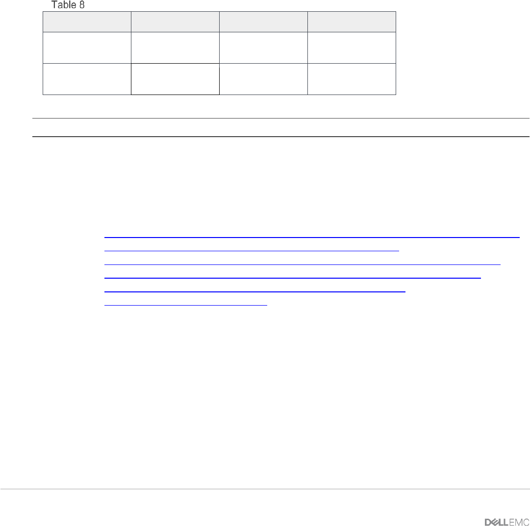
For the example shown here in Section 10.3 and 10.4, The uplink attributes are defined here.
Uplink attributes
Uplink Name
Description
Ports
VLAN (Tagged)
FCoE A1
FC Uplink for
switch in Slot A1
Switch model
dependent
30
FCoE A2
FC Uplink for
switch in Slot A2
Switch model
dependent
40
Note: Do not assign the same FCoE VLAN to both switches. They must be kept separate.
4.8 Configuring the upstream switch and connect uplink cables
The upstream switch ports must be configured in a single LACP LAG. This document provides six example
configurations. The first three example configurations are for ethernet uplinks and other three scenarios are
for storage.
• Scenario 1: SmartFabric deployment with Dell EMC PowerSwitch Z9100-ON upstream switches
• Scenario 2: SmartFabric connected to Cisco Nexus 3232C switches
• Scenario 3: Connect MX9116n FSE to Fibre Channel Storage – NPIV Proxy gateway mode
• Scenario 4: Connect MX9116n FSE to Fibre Channel Storage – FC Direct attach mode
• Scenario 5: Connect MX5108n to Fibre Channel Storage - FSB mode
• Scenario 6: Configure Boot from SAN