
Users Guide
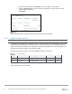
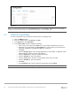

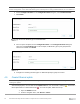

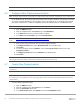
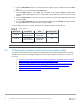
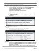
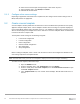
Table Of Contents
- 1 Introduction
- 2 SmartFabric Services for PowerEdge MX: An overview
- 3 SmartFabric mode requirements, guidelines, and restrictions
- 3.1 Create multi-chassis management group
- 3.2 Upstream network requirements
- 3.3 VLAN scaling guidelines
- 3.4 Configuring port speed and breakout
- 3.5 Switch slot placement for SmartFabric mode
- 3.6 Switch-to-Switch cabling
- 3.7 NIC teaming guidelines
- 3.8 Maximum Transmission Unit (MTU) behavior
- 3.9 Other restrictions and guidelines
- 4 Creating a SmartFabric
- 4.1 Physically cable MX chassis and upstream switches
- 4.2 Define VLANs
- 4.3 Create the SmartFabric
- 4.4 Configure uplink port speed or breakout, if needed
- 4.5 Create Ethernet uplink
- 4.6 Configure Fibre Channel universal ports
- 4.7 Create Fibre Channel uplinks
- 4.8 Configuring the upstream switch and connect uplink cables
- 5 Deploying a server
- 6 SmartFabric operations
- 7 Switch operations
- 8 Validating the SmartFabric deployment
- 9 SmartFabric troubleshooting
- 9.1 Troubleshooting errors encountered for port group breakout
- 9.2 Troubleshooting Spanning Tree Protocol (STP)
- 9.3 Verify VLT/vPC configuration on upstream switches
- 9.4 Discovery of FEM and compute sleds
- 9.5 Troubleshooting uplink errors
- 9.6 Troubleshooting FC/FCoE
- 9.7 SmartFabric Services – Troubleshooting commands
- 10 Uplink configuration scenarios
- 10.1 Scenario 1 - SmartFabric deployment with Dell EMC PowerSwitch Z9100-ON upstream switches
- 10.2 Scenario 2 - SmartFabric connected to Cisco Nexus 3232C switches
- 10.3 Scenario 3: Connect MX9116n FSE to Fibre Channel storage - NPIV Proxy Gateway mode
- 10.4 Scenario 4: Connect MX9116n FSE to Fibre Channel storage - FC Direct Attach
- 10.5 Scenario 5: Connect MX5108n to Fibre Channel storage - FSB
- 10.6 Scenario 6: Configure Boot from SAN
- A Hardware used in this document
- B Dell EMC Unity information
- C Additional information
- D Validated components
- E Technical resources
- F Support and feedback
33 Dell EMC PowerEdge MX SmartFabric Configuration and Troubleshooting Guide
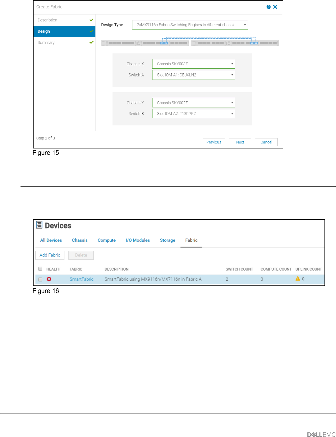
SmartFabric deployment design window
The SmartFabric deploys. This process can take several minutes to complete. During this time all related
switches will be rebooted, and the operating mode changed to SmartFabric mode.
Note: After the fabric is created, the fabric health will be critical until at least one uplink is created.
Figure 16 shows the new SmartFabric object and some basic information about the fabric.
SmartFabric post-deployment without defined uplinks
4.4 Configure uplink port speed or breakout, if needed
If the uplink ports need to be reconfigured to a different speed or breakout setting from the default, you must
do that before creating the actual uplink.
To configure the Ethernet breakout on port groups using OME-M Console, perform the following steps:
1. Open the OME-M console.
2. From the navigation menu, click Devices > I/O Modules.
3. Select the switch you want to manage. In this example, a MX9116n FSE in slot IOM-A1 is selected.
4. Choose Hardware > Port Information.
5. In the Port Information pane, choose the desired port-group. In this example port-group1/1/13 is
selected.