
Users Guide
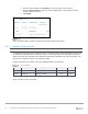
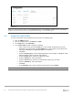

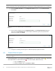

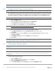
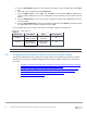
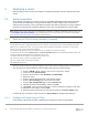
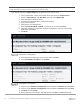
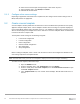
Table Of Contents
- 1 Introduction
- 2 SmartFabric Services for PowerEdge MX: An overview
- 3 SmartFabric mode requirements, guidelines, and restrictions
- 3.1 Create multi-chassis management group
- 3.2 Upstream network requirements
- 3.3 VLAN scaling guidelines
- 3.4 Configuring port speed and breakout
- 3.5 Switch slot placement for SmartFabric mode
- 3.6 Switch-to-Switch cabling
- 3.7 NIC teaming guidelines
- 3.8 Maximum Transmission Unit (MTU) behavior
- 3.9 Other restrictions and guidelines
- 4 Creating a SmartFabric
- 4.1 Physically cable MX chassis and upstream switches
- 4.2 Define VLANs
- 4.3 Create the SmartFabric
- 4.4 Configure uplink port speed or breakout, if needed
- 4.5 Create Ethernet uplink
- 4.6 Configure Fibre Channel universal ports
- 4.7 Create Fibre Channel uplinks
- 4.8 Configuring the upstream switch and connect uplink cables
- 5 Deploying a server
- 6 SmartFabric operations
- 7 Switch operations
- 8 Validating the SmartFabric deployment
- 9 SmartFabric troubleshooting
- 9.1 Troubleshooting errors encountered for port group breakout
- 9.2 Troubleshooting Spanning Tree Protocol (STP)
- 9.3 Verify VLT/vPC configuration on upstream switches
- 9.4 Discovery of FEM and compute sleds
- 9.5 Troubleshooting uplink errors
- 9.6 Troubleshooting FC/FCoE
- 9.7 SmartFabric Services – Troubleshooting commands
- 10 Uplink configuration scenarios
- 10.1 Scenario 1 - SmartFabric deployment with Dell EMC PowerSwitch Z9100-ON upstream switches
- 10.2 Scenario 2 - SmartFabric connected to Cisco Nexus 3232C switches
- 10.3 Scenario 3: Connect MX9116n FSE to Fibre Channel storage - NPIV Proxy Gateway mode
- 10.4 Scenario 4: Connect MX9116n FSE to Fibre Channel storage - FC Direct Attach
- 10.5 Scenario 5: Connect MX5108n to Fibre Channel storage - FSB
- 10.6 Scenario 6: Configure Boot from SAN
- A Hardware used in this document
- B Dell EMC Unity information
- C Additional information
- D Validated components
- E Technical resources
- F Support and feedback
32 Dell EMC PowerEdge MX SmartFabric Configuration and Troubleshooting Guide
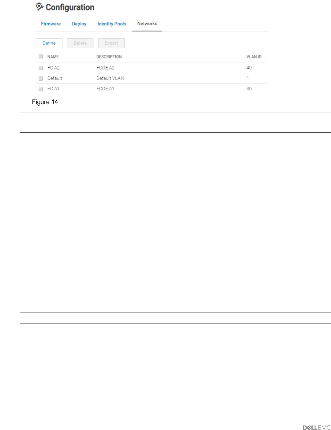
Defined VLAN list
Note: To create VLANs for FCoE, From the Network Type list, select Storage – FCoE, and then click Finish.
VLANs to be used for FCoE must be configured as the Storage – FCoE network type.
4.3 Create the SmartFabric
To create a SmartFabric using the OME-M console, perform the following steps:
1. Open the OME-M console.
2. From the navigation menu, click Devices > Fabric.
3. In the Fabric pane, click Add Fabric.
4. In the Create Fabric window, complete the following:
• Enter a name for the fabric in the Name box. In this example, SmartFabric was entered.
• Optionally, enter a description in the Description box. In this example, the description was
entered as “SmartFabric using MX9116n/MX7116n in Fabric A”.
• Click Next.
• From the Design Type list, select the appropriate type. In this example, “2x MX9116n Fabric
Switching Engine in different chassis” was selected.
• From the Chassis-X list, select the first MX7000 chassis.
• From the Switch-A list, select Slot-IOM-A1.
• From the Chassis-Y list, select the second MX7000 chassis to join the fabric.
• From the Switch-B list, select Slot-IOM-A2.
• Click Next.
• On the Summary page, verify the proposed configuration and click Finish.
Note: From the Summary window a list of the physical cabling requirements can be printed.