
Users Guide
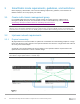
Table Of Contents
- 1 Introduction
- 2 SmartFabric Services for PowerEdge MX: An overview
- 3 SmartFabric mode requirements, guidelines, and restrictions
- 3.1 Create multi-chassis management group
- 3.2 Upstream network requirements
- 3.3 VLAN scaling guidelines
- 3.4 Configuring port speed and breakout
- 3.5 Switch slot placement for SmartFabric mode
- 3.6 Switch-to-Switch cabling
- 3.7 NIC teaming guidelines
- 3.8 Maximum Transmission Unit (MTU) behavior
- 3.9 Other restrictions and guidelines
- 4 Creating a SmartFabric
- 4.1 Physically cable MX chassis and upstream switches
- 4.2 Define VLANs
- 4.3 Create the SmartFabric
- 4.4 Configure uplink port speed or breakout, if needed
- 4.5 Create Ethernet uplink
- 4.6 Configure Fibre Channel universal ports
- 4.7 Create Fibre Channel uplinks
- 4.8 Configuring the upstream switch and connect uplink cables
- 5 Deploying a server
- 6 SmartFabric operations
- 7 Switch operations
- 8 Validating the SmartFabric deployment
- 9 SmartFabric troubleshooting
- 9.1 Troubleshooting errors encountered for port group breakout
- 9.2 Troubleshooting Spanning Tree Protocol (STP)
- 9.3 Verify VLT/vPC configuration on upstream switches
- 9.4 Discovery of FEM and compute sleds
- 9.5 Troubleshooting uplink errors
- 9.6 Troubleshooting FC/FCoE
- 9.7 SmartFabric Services – Troubleshooting commands
- 10 Uplink configuration scenarios
- 10.1 Scenario 1 - SmartFabric deployment with Dell EMC PowerSwitch Z9100-ON upstream switches
- 10.2 Scenario 2 - SmartFabric connected to Cisco Nexus 3232C switches
- 10.3 Scenario 3: Connect MX9116n FSE to Fibre Channel storage - NPIV Proxy Gateway mode
- 10.4 Scenario 4: Connect MX9116n FSE to Fibre Channel storage - FC Direct Attach
- 10.5 Scenario 5: Connect MX5108n to Fibre Channel storage - FSB
- 10.6 Scenario 6: Configure Boot from SAN
- A Hardware used in this document
- B Dell EMC Unity information
- C Additional information
- D Validated components
- E Technical resources
- F Support and feedback
30 Dell EMC PowerEdge MX SmartFabric Configuration and Troubleshooting Guide
4 Creating a SmartFabric
The general steps required to create a SmartFabric are:
1. Physically cable the MX chassis and upstream switches.
2. Define the VLANs.
3. Create the SmartFabric.
4. If needed, configure uplink port speed and breakout.
5. Create the Ethernet uplink.
6. Configure the upstream switch and connect uplink cables.
These steps make the following assumptions:
• All MX7000 chassis and management modules are cabled correctly and in a Multi-Chassis
Management group.
• The VLTi cables between switches have been connected.
• Open Manage Enterprise - Modular is at version 1.10.00 and OS10 is version 10.5.0.1
Note: All server, network, and chassis hardware has been updated to the latest firmware. See Appendix D for the
minimum recommended firmware versions.
4.1 Physically cable MX chassis and upstream switches
The first step in creating the SmartFabric is to cable the MX chassis and upstream switches.
• For Management Module cabling, see Dell EMC PowerEdge MX Networking Architecture Guide.
• For VLTi cabling of different IOM placements, see Figure 8, Figure 9, and Figure 10.
For information on cabling the MX chassis to the upstream switches, see the example topologies in Section
10 in this document.
For further information on cabling PowerEdge MX in general, see Dell EMC PowerEdge MX Networking
Architecture Guide.
4.2 Define VLANs
Before creating the SmartFabric, the initial set of VLANs should be created. The first VLAN to be created
should be the default, or native VLAN, typically VLAN 1. The default VLAN must be created for any untagged
traffic to cross the fabric.
Note: VLAN1 will be created as a Default VLAN when the first fabric is created.
To define VLANs using the OME-M console, perform the following steps:
1. Open the OME-M console.
2. From the navigation menu, click Configuration > Networks.
3. In the Network pane, click Define.
4. In the Define Network window, complete the following:
• Enter a name for the VLAN in the Name box. In this example, VLAN0010 was used.
• Optionally, enter a description in the Description box. In this example, the description was
entered as “Company A General Purpose”.