
Users Guide
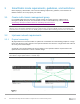
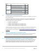
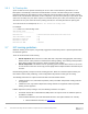
Table Of Contents
- 1 Introduction
- 2 SmartFabric Services for PowerEdge MX: An overview
- 3 SmartFabric mode requirements, guidelines, and restrictions
- 3.1 Create multi-chassis management group
- 3.2 Upstream network requirements
- 3.3 VLAN scaling guidelines
- 3.4 Configuring port speed and breakout
- 3.5 Switch slot placement for SmartFabric mode
- 3.6 Switch-to-Switch cabling
- 3.7 NIC teaming guidelines
- 3.8 Maximum Transmission Unit (MTU) behavior
- 3.9 Other restrictions and guidelines
- 4 Creating a SmartFabric
- 4.1 Physically cable MX chassis and upstream switches
- 4.2 Define VLANs
- 4.3 Create the SmartFabric
- 4.4 Configure uplink port speed or breakout, if needed
- 4.5 Create Ethernet uplink
- 4.6 Configure Fibre Channel universal ports
- 4.7 Create Fibre Channel uplinks
- 4.8 Configuring the upstream switch and connect uplink cables
- 5 Deploying a server
- 6 SmartFabric operations
- 7 Switch operations
- 8 Validating the SmartFabric deployment
- 9 SmartFabric troubleshooting
- 9.1 Troubleshooting errors encountered for port group breakout
- 9.2 Troubleshooting Spanning Tree Protocol (STP)
- 9.3 Verify VLT/vPC configuration on upstream switches
- 9.4 Discovery of FEM and compute sleds
- 9.5 Troubleshooting uplink errors
- 9.6 Troubleshooting FC/FCoE
- 9.7 SmartFabric Services – Troubleshooting commands
- 10 Uplink configuration scenarios
- 10.1 Scenario 1 - SmartFabric deployment with Dell EMC PowerSwitch Z9100-ON upstream switches
- 10.2 Scenario 2 - SmartFabric connected to Cisco Nexus 3232C switches
- 10.3 Scenario 3: Connect MX9116n FSE to Fibre Channel storage - NPIV Proxy Gateway mode
- 10.4 Scenario 4: Connect MX9116n FSE to Fibre Channel storage - FC Direct Attach
- 10.5 Scenario 5: Connect MX5108n to Fibre Channel storage - FSB
- 10.6 Scenario 6: Configure Boot from SAN
- A Hardware used in this document
- B Dell EMC Unity information
- C Additional information
- D Validated components
- E Technical resources
- F Support and feedback
28 Dell EMC PowerEdge MX SmartFabric Configuration and Troubleshooting Guide
2. Microsoft Windows 2016, see Instructions
Refer to the network adapter or operating system documentation for detailed NIC teaming instructions.
Note: If using VMware ESXi and LACP, it is recommended to use VMware ESXi 6.7.0 Update 2.
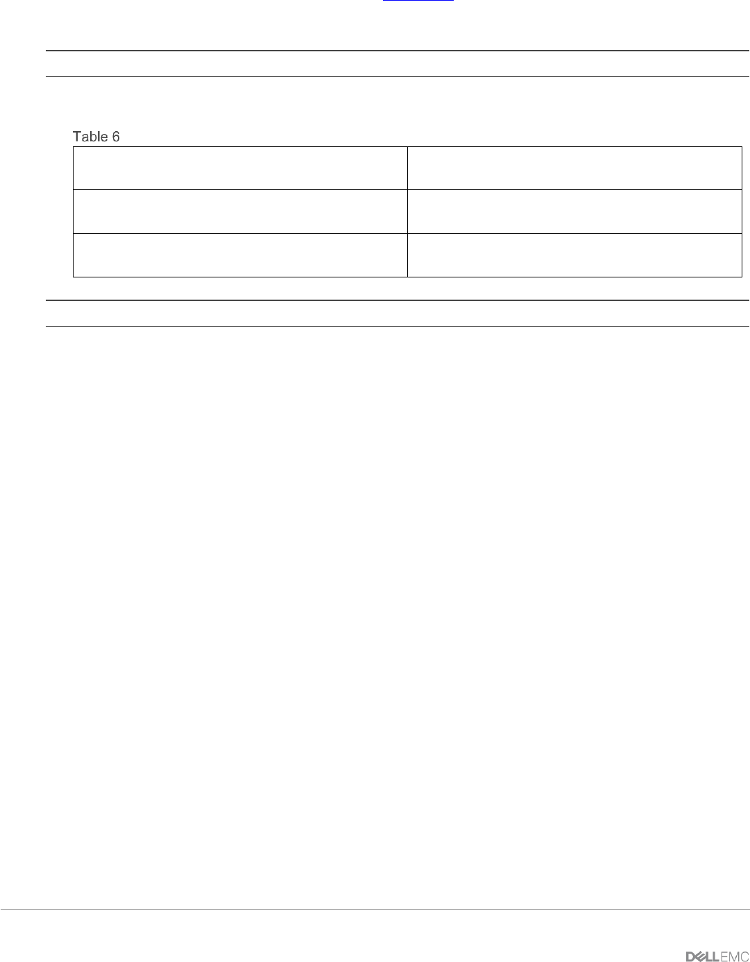
Table 6 shows the options that MX Platform provides for NIC Teaming.
NIC Teaming Options on MX Platform
No Teaming
No NIC Bonding/Teaming or Switch Independent
Teaming
LACP Teaming
LACP (Also called 802.3ad or Dynamic Link
Aggregation)
Other
Other (Not recommended. Can have performance
impact on link management)
Note: LACP Fast timer is not currently supported.
3.8 Maximum Transmission Unit (MTU) behavior
The default MTU for SmartFabric OS10 interfaces is 1532 bytes. When a SmartFabric is created, the default
MTU for the switch is set to Jumbo (9216 bytes). This introduces the following behaviors:
1. If the MTU is not specifically set on a specific interface, the MTU will be 9216 bytes.
2. If the MTU has been specifically set on a specific interface, the MTU will be the value that has
been specified.
3. If a FCoE VLAN is assigned to an interface, the MTU will be set to 2500 bytes even if the
MTU had been manually set to a different value before the FCoE VLAN was assigned. It is
recommended that you set the MTU back to 9216 bytes after the FCoE VLAN has been
assigned
Please see Section 7.2 for instructions on setting the MTU.
3.9 Other restrictions and guidelines
The following additional restrictions and guidelines are in place when operating in SmartFabric mode:
1. Interconnecting switches in Slots A1/A2 with switches in Slots B1/B2 regardless of chassis is not
supported.
2. When operating with multiple chassis, switches in Slots A1/A2 or Slots B1/B2 in one chassis must be
interconnected only with other Slots A1/A2 or Slots B1/B2 switches respectively. Connecting switches
that reside in Slots A1/A2 in one chassis with switches in Slots B1/B2 in another is not supported.
3. Uplinks must be symmetrical. If one switch in a SmartFabric has two uplinks, the other switch must have
two uplinks of the same speed.
4. You cannot have a pair of switches in SmartFabric mode uplink to another pair of switches in SmartFabric
mode. A SmartFabric can uplink to a pair of switches in Full Switch mode.
5. VLANs 4001 to 4020 are reserved for internal switch communication and must not be assigned to an
interface.