
Users Guide
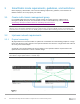
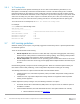
Table Of Contents
- 1 Introduction
- 2 SmartFabric Services for PowerEdge MX: An overview
- 3 SmartFabric mode requirements, guidelines, and restrictions
- 3.1 Create multi-chassis management group
- 3.2 Upstream network requirements
- 3.3 VLAN scaling guidelines
- 3.4 Configuring port speed and breakout
- 3.5 Switch slot placement for SmartFabric mode
- 3.6 Switch-to-Switch cabling
- 3.7 NIC teaming guidelines
- 3.8 Maximum Transmission Unit (MTU) behavior
- 3.9 Other restrictions and guidelines
- 4 Creating a SmartFabric
- 4.1 Physically cable MX chassis and upstream switches
- 4.2 Define VLANs
- 4.3 Create the SmartFabric
- 4.4 Configure uplink port speed or breakout, if needed
- 4.5 Create Ethernet uplink
- 4.6 Configure Fibre Channel universal ports
- 4.7 Create Fibre Channel uplinks
- 4.8 Configuring the upstream switch and connect uplink cables
- 5 Deploying a server
- 6 SmartFabric operations
- 7 Switch operations
- 8 Validating the SmartFabric deployment
- 9 SmartFabric troubleshooting
- 9.1 Troubleshooting errors encountered for port group breakout
- 9.2 Troubleshooting Spanning Tree Protocol (STP)
- 9.3 Verify VLT/vPC configuration on upstream switches
- 9.4 Discovery of FEM and compute sleds
- 9.5 Troubleshooting uplink errors
- 9.6 Troubleshooting FC/FCoE
- 9.7 SmartFabric Services – Troubleshooting commands
- 10 Uplink configuration scenarios
- 10.1 Scenario 1 - SmartFabric deployment with Dell EMC PowerSwitch Z9100-ON upstream switches
- 10.2 Scenario 2 - SmartFabric connected to Cisco Nexus 3232C switches
- 10.3 Scenario 3: Connect MX9116n FSE to Fibre Channel storage - NPIV Proxy Gateway mode
- 10.4 Scenario 4: Connect MX9116n FSE to Fibre Channel storage - FC Direct Attach
- 10.5 Scenario 5: Connect MX5108n to Fibre Channel storage - FSB
- 10.6 Scenario 6: Configure Boot from SAN
- A Hardware used in this document
- B Dell EMC Unity information
- C Additional information
- D Validated components
- E Technical resources
- F Support and feedback

27 Dell EMC PowerEdge MX SmartFabric Configuration and Troubleshooting Guide
3.6.1 VLT backup link
A pair of cables is used to provide redundancy for the VLTi link. A third redundancy mechanism, a VLT
backup link is automatically created when the SmartFabric is created. This link exchanges VLT heartbeat
information between the two switches to avoid a split-brain scenario should the external VLTi links go down.
Based on the node liveliness information, the VLT LAG/port is in up state in the primary VLT peer and in down
state in the secondary VLT peer. When only the VLTi link fails, but the peer is alive, the secondary VLT peer
shuts down the VLT ports. When the node in primary peer fails, the secondary becomes the primary peer.
To see the status of VLT backup link, run show vlt domain-id backup-link.
For example:
OS10# show vlt 255 backup-link
VLT Backup Link
------------------------
Destination : fde1:53ba:e9a0:de14:2204:fff:fe00:a267
Peer Heartbeat status : Up
Heartbeat interval : 30
Heartbeat timeout : 90
Destination VRF : default
3.7 NIC teaming guidelines
While NIC teaming is not required, it is generally suggested for redundancy unless a specific implementation
recommends against it.
There are two main kinds of NIC teaming:
• Switch dependent: Also referred to as LACP, 802.3ad, or Dynamic Link Aggregation, this teaming
method uses the LACP protocol to understand the teaming topology. This teaming method provides
Active-Active teaming and requires the switch to support LACP teaming.
• Switch independent: This method uses the operating system and NIC device drivers on the server
to team the NICs. Each NIC vendor may provide slightly different implementations with different pros
and cons.
NIC Partitioning (NPAR) can impact how NIC teaming operates. Based on restrictions implemented by the
NIC vendors related to NIC partitioning, certain configurations will preclude certain types of teaming.
The following restrictions are in place for both Full Switch and SmartFabric modes:
• If NPAR is NOT in use, both Switch Dependent (LACP) and Switch Independent teaming methods
are supported
• If NPAR IS in use, only Switch Independent teaming methods are supported. Switch Dependent
teaming is NOT supported
If Switch Dependent (LACP) teaming is used, the following restrictions are in place:
• The iDRAC shared LAN on motherboard (LOM) feature can only be used if the “Failover” option on
the iDRAC is enabled
• If the host OS is Windows, the LACP timer MUST be set to “slow” (also referred to as “normal”)
1. Microsoft Windows 2012 R2, see Instructions