
Users Guide
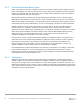
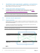
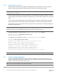
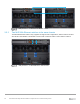
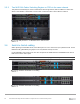
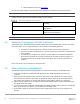
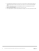
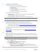
Table Of Contents
- 1 Introduction
- 2 SmartFabric Services for PowerEdge MX: An overview
- 3 SmartFabric mode requirements, guidelines, and restrictions
- 3.1 Create multi-chassis management group
- 3.2 Upstream network requirements
- 3.3 VLAN scaling guidelines
- 3.4 Configuring port speed and breakout
- 3.5 Switch slot placement for SmartFabric mode
- 3.6 Switch-to-Switch cabling
- 3.7 NIC teaming guidelines
- 3.8 Maximum Transmission Unit (MTU) behavior
- 3.9 Other restrictions and guidelines
- 4 Creating a SmartFabric
- 4.1 Physically cable MX chassis and upstream switches
- 4.2 Define VLANs
- 4.3 Create the SmartFabric
- 4.4 Configure uplink port speed or breakout, if needed
- 4.5 Create Ethernet uplink
- 4.6 Configure Fibre Channel universal ports
- 4.7 Create Fibre Channel uplinks
- 4.8 Configuring the upstream switch and connect uplink cables
- 5 Deploying a server
- 6 SmartFabric operations
- 7 Switch operations
- 8 Validating the SmartFabric deployment
- 9 SmartFabric troubleshooting
- 9.1 Troubleshooting errors encountered for port group breakout
- 9.2 Troubleshooting Spanning Tree Protocol (STP)
- 9.3 Verify VLT/vPC configuration on upstream switches
- 9.4 Discovery of FEM and compute sleds
- 9.5 Troubleshooting uplink errors
- 9.6 Troubleshooting FC/FCoE
- 9.7 SmartFabric Services – Troubleshooting commands
- 10 Uplink configuration scenarios
- 10.1 Scenario 1 - SmartFabric deployment with Dell EMC PowerSwitch Z9100-ON upstream switches
- 10.2 Scenario 2 - SmartFabric connected to Cisco Nexus 3232C switches
- 10.3 Scenario 3: Connect MX9116n FSE to Fibre Channel storage - NPIV Proxy Gateway mode
- 10.4 Scenario 4: Connect MX9116n FSE to Fibre Channel storage - FC Direct Attach
- 10.5 Scenario 5: Connect MX5108n to Fibre Channel storage - FSB
- 10.6 Scenario 6: Configure Boot from SAN
- A Hardware used in this document
- B Dell EMC Unity information
- C Additional information
- D Validated components
- E Technical resources
- F Support and feedback
26 Dell EMC PowerEdge MX SmartFabric Configuration and Troubleshooting Guide
3.5.3 Two MX9116n Fabric Switching Engines or FSEs in the same chassis
This placement should only be used in environments with a single chassis, with the switches in either slots
A1/A2 or slots B1/B2. A SmartFabric cannot include a switch in Fabric A and a switch in Fabric B.
IOM placement – 2 x MX9116n in the same chassis
3.6 Switch-to-Switch cabling
When operating in SmartFabric mode, each switch pair runs a VLT interconnect (VLTi) between them. For the
MX9116n FSE, QSFP28-DD port groups 11 and 12 (eth1/1/37-1/1/40) are used.
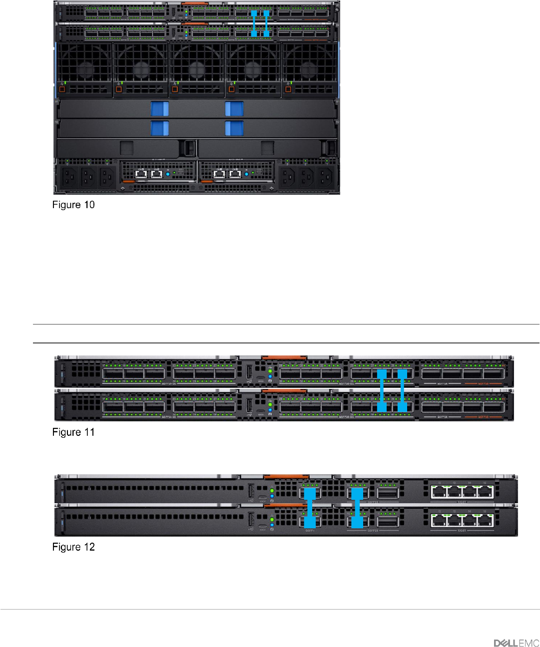
For the MX5108n, ports 9 and 10 are used. Port 10 operates at 40GbE instead of 100GbE because all VLTi
links must run at the same speed.
Note: The VLTi ports are not user selectable and the connection topology is enforced by the SmartFabric engine.
MX9116n SmartFabric VLTi cabling
MX5108n SmartFabric VLTi cabling