
Users Guide
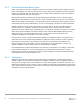
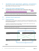
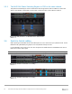
Table Of Contents
- 1 Introduction
- 2 SmartFabric Services for PowerEdge MX: An overview
- 3 SmartFabric mode requirements, guidelines, and restrictions
- 3.1 Create multi-chassis management group
- 3.2 Upstream network requirements
- 3.3 VLAN scaling guidelines
- 3.4 Configuring port speed and breakout
- 3.5 Switch slot placement for SmartFabric mode
- 3.6 Switch-to-Switch cabling
- 3.7 NIC teaming guidelines
- 3.8 Maximum Transmission Unit (MTU) behavior
- 3.9 Other restrictions and guidelines
- 4 Creating a SmartFabric
- 4.1 Physically cable MX chassis and upstream switches
- 4.2 Define VLANs
- 4.3 Create the SmartFabric
- 4.4 Configure uplink port speed or breakout, if needed
- 4.5 Create Ethernet uplink
- 4.6 Configure Fibre Channel universal ports
- 4.7 Create Fibre Channel uplinks
- 4.8 Configuring the upstream switch and connect uplink cables
- 5 Deploying a server
- 6 SmartFabric operations
- 7 Switch operations
- 8 Validating the SmartFabric deployment
- 9 SmartFabric troubleshooting
- 9.1 Troubleshooting errors encountered for port group breakout
- 9.2 Troubleshooting Spanning Tree Protocol (STP)
- 9.3 Verify VLT/vPC configuration on upstream switches
- 9.4 Discovery of FEM and compute sleds
- 9.5 Troubleshooting uplink errors
- 9.6 Troubleshooting FC/FCoE
- 9.7 SmartFabric Services – Troubleshooting commands
- 10 Uplink configuration scenarios
- 10.1 Scenario 1 - SmartFabric deployment with Dell EMC PowerSwitch Z9100-ON upstream switches
- 10.2 Scenario 2 - SmartFabric connected to Cisco Nexus 3232C switches
- 10.3 Scenario 3: Connect MX9116n FSE to Fibre Channel storage - NPIV Proxy Gateway mode
- 10.4 Scenario 4: Connect MX9116n FSE to Fibre Channel storage - FC Direct Attach
- 10.5 Scenario 5: Connect MX5108n to Fibre Channel storage - FSB
- 10.6 Scenario 6: Configure Boot from SAN
- A Hardware used in this document
- B Dell EMC Unity information
- C Additional information
- D Validated components
- E Technical resources
- F Support and feedback
22 Dell EMC PowerEdge MX SmartFabric Configuration and Troubleshooting Guide
3 SmartFabric mode requirements, guidelines, and restrictions
Before deploying a SmartFabric, ensure that the following requirements, guidelines, and restrictions are
followed. Failure to do so may impact your network.
3.1 Create multi-chassis management group
For a scalable fabric that uses more than one MX chassis, the chassis must be in a Multi-Chassis
Management (MCM) Group. For more information on how to create MCM Group, refer to Dell EMC
OpenManage Enterprise-Modular Edition for PowerEdge MX7000 Chassis.
Note: SmartFabric mode can be enabled on a single chassis having two MX9116n FSEs or two MX5108n
switches. For a SmartFabric implemented using a single chassis, creating an MCM group is not mandatory but
recommended. The chassis must be in an MCM group for a SmartFabric containing more than one MX chassis.
3.2 Upstream network requirements
3.2.1 Physical connectivity
All physical Ethernet connections within an uplink from a SmartFabric are automatically grouped into a single
LACP LAG. Because of this, all ports on the upstream switches must also be in a single LACP LAG. Failure to
do so may create network loops.
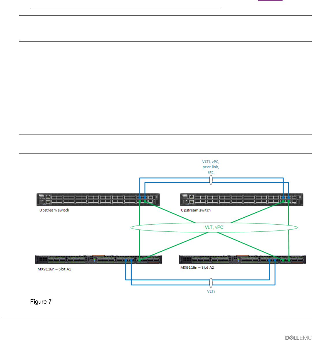
A minimum of one physical uplink from each MX switch to each upstream switch is required and that the
uplinks must be connected in a “mesh” or “bowtie” design.
Note: The upstream switch ports must be in a single LACP LAG as shown in the figure below. Creating multiple
LAGs within a single uplink results in a network loop.
Recommended upstream network connectivity