
Users Guide
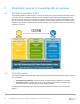
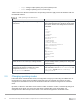
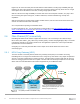
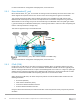
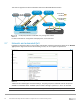
Table Of Contents
- 1 Introduction
- 2 SmartFabric Services for PowerEdge MX: An overview
- 3 SmartFabric mode requirements, guidelines, and restrictions
- 3.1 Create multi-chassis management group
- 3.2 Upstream network requirements
- 3.3 VLAN scaling guidelines
- 3.4 Configuring port speed and breakout
- 3.5 Switch slot placement for SmartFabric mode
- 3.6 Switch-to-Switch cabling
- 3.7 NIC teaming guidelines
- 3.8 Maximum Transmission Unit (MTU) behavior
- 3.9 Other restrictions and guidelines
- 4 Creating a SmartFabric
- 4.1 Physically cable MX chassis and upstream switches
- 4.2 Define VLANs
- 4.3 Create the SmartFabric
- 4.4 Configure uplink port speed or breakout, if needed
- 4.5 Create Ethernet uplink
- 4.6 Configure Fibre Channel universal ports
- 4.7 Create Fibre Channel uplinks
- 4.8 Configuring the upstream switch and connect uplink cables
- 5 Deploying a server
- 6 SmartFabric operations
- 7 Switch operations
- 8 Validating the SmartFabric deployment
- 9 SmartFabric troubleshooting
- 9.1 Troubleshooting errors encountered for port group breakout
- 9.2 Troubleshooting Spanning Tree Protocol (STP)
- 9.3 Verify VLT/vPC configuration on upstream switches
- 9.4 Discovery of FEM and compute sleds
- 9.5 Troubleshooting uplink errors
- 9.6 Troubleshooting FC/FCoE
- 9.7 SmartFabric Services – Troubleshooting commands
- 10 Uplink configuration scenarios
- 10.1 Scenario 1 - SmartFabric deployment with Dell EMC PowerSwitch Z9100-ON upstream switches
- 10.2 Scenario 2 - SmartFabric connected to Cisco Nexus 3232C switches
- 10.3 Scenario 3: Connect MX9116n FSE to Fibre Channel storage - NPIV Proxy Gateway mode
- 10.4 Scenario 4: Connect MX9116n FSE to Fibre Channel storage - FC Direct Attach
- 10.5 Scenario 5: Connect MX5108n to Fibre Channel storage - FSB
- 10.6 Scenario 6: Configure Boot from SAN
- A Hardware used in this document
- B Dell EMC Unity information
- C Additional information
- D Validated components
- E Technical resources
- F Support and feedback
17 Dell EMC PowerEdge MX SmartFabric Configuration and Troubleshooting Guide
logical unit, the control and data plane of both switches remain isolated, ensuring high availability and high
resilience for all its connected devices. This differs from the legacy stacking concept, where there is a single
control plane across all switches in the stack, creating a single point of failure.
With the critical need for high availability in modern data centers and enterprise networks, VLT plays a vital
role connecting with rapid convergence, seamless traffic flow, efficient load balancing, and loop free
capabilities.
With the instantaneous synchronization of MAC and ARP entries, both the nodes remain Active-Active and
continue to forward the data traffic seamlessly.
VLT is required when operating in SmartFabric mode.
For more information on VLT, see the Virtual Link Trunking chapter in the OS10 Enterprise Edition User
Guide - PowerEdge MX I/O Modules and Virtual Link Trunking (VLT) in Dell EMC OS10 Enterprise Edition
Best Practices and Deployment Guide.
2.6 Fibre Channel (FC) connectivity
PowerEdge MX Ethernet I/O modules support Fibre Channel, or FC connectivity in three different ways:
Direct Attach (also called F_port), NPIV Proxy Gateway (NPG), and FIP Snooping Bridge (FSB). The method
to implement depends on the existing infrastructure and application requirements. Consult your Dell EMC
representative for more information.
Configuring FC connectivity in SmartFabric mode is simple and is almost identical across the three
connectivity types.
2.6.1 NPIV Proxy Gateway (NPG)
The most common connectivity method, NPIV Proxy Gateway mode (NPG) is used when connecting
PowerEdge MX to a storage area network that hosts a storage array. NPG mode is very simple to implement
as there is very little configuration that needs to be done. The NPG switch converts FCoE from the server to
native FC and aggregates the traffic into an uplink. The NPG switch is effectively transparent to the FC SAN,
which “sees” the hosts themselves. This mode is supported only on the MX9116n FSE.
FC Switch
FC Switch
MX9116n
(Leaf 2)
MX9116n
(Leaf 1)
VLT
MX7000
Spine 2
Spine 1
FC SAN A
Note: Brocade 6510 switches were used in
validating this brownfield example. Other FC
switches may be used as well.
Unity 500F
Unity 500F
Unity 500F
Controller A Controller B
chassis 1
MX7000
chassis 2
FC SAN B
FC (NPG) network to Dell EMC Unity