
Users Guide
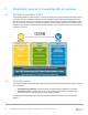
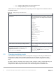
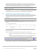
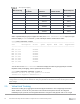
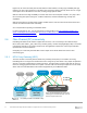
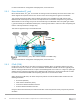
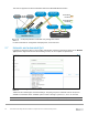
Table Of Contents
- 1 Introduction
- 2 SmartFabric Services for PowerEdge MX: An overview
- 3 SmartFabric mode requirements, guidelines, and restrictions
- 3.1 Create multi-chassis management group
- 3.2 Upstream network requirements
- 3.3 VLAN scaling guidelines
- 3.4 Configuring port speed and breakout
- 3.5 Switch slot placement for SmartFabric mode
- 3.6 Switch-to-Switch cabling
- 3.7 NIC teaming guidelines
- 3.8 Maximum Transmission Unit (MTU) behavior
- 3.9 Other restrictions and guidelines
- 4 Creating a SmartFabric
- 4.1 Physically cable MX chassis and upstream switches
- 4.2 Define VLANs
- 4.3 Create the SmartFabric
- 4.4 Configure uplink port speed or breakout, if needed
- 4.5 Create Ethernet uplink
- 4.6 Configure Fibre Channel universal ports
- 4.7 Create Fibre Channel uplinks
- 4.8 Configuring the upstream switch and connect uplink cables
- 5 Deploying a server
- 6 SmartFabric operations
- 7 Switch operations
- 8 Validating the SmartFabric deployment
- 9 SmartFabric troubleshooting
- 9.1 Troubleshooting errors encountered for port group breakout
- 9.2 Troubleshooting Spanning Tree Protocol (STP)
- 9.3 Verify VLT/vPC configuration on upstream switches
- 9.4 Discovery of FEM and compute sleds
- 9.5 Troubleshooting uplink errors
- 9.6 Troubleshooting FC/FCoE
- 9.7 SmartFabric Services – Troubleshooting commands
- 10 Uplink configuration scenarios
- 10.1 Scenario 1 - SmartFabric deployment with Dell EMC PowerSwitch Z9100-ON upstream switches
- 10.2 Scenario 2 - SmartFabric connected to Cisco Nexus 3232C switches
- 10.3 Scenario 3: Connect MX9116n FSE to Fibre Channel storage - NPIV Proxy Gateway mode
- 10.4 Scenario 4: Connect MX9116n FSE to Fibre Channel storage - FC Direct Attach
- 10.5 Scenario 5: Connect MX5108n to Fibre Channel storage - FSB
- 10.6 Scenario 6: Configure Boot from SAN
- A Hardware used in this document
- B Dell EMC Unity information
- C Additional information
- D Validated components
- E Technical resources
- F Support and feedback
16 Dell EMC PowerEdge MX SmartFabric Configuration and Troubleshooting Guide
Virtual port mapping
FEM service tag
FSE QSFP28-DD
port group
FSE 25G
interfaces
FEM unit ID
(virtual slot ID)
FEM virtual ports
12AB3456
portgroup1/1/1
1/1/17:1
71
1/71/1
1/1/17:2
1/71/2
1/1/17:3
1/71/3
1/1/17:4
1/71/4
1/1/18:1
1/71/5
1/1/18:2
1/71/6
1/1/18:3
1/71/7
1/1/18:4
1/71/8
When a QSFP28-DD port group is mapped to a FEM, in the show interface status output, the eight
interfaces display dormant instead of up until a virtual port starts to transmit server traffic:
OS10# show interface status
--------------------------------------------------------------------------------
Port Description Status Speed Duplex Mode Vlan Tagged-Vlans
--------------------------------------------------------------------------------
...
Eth 1/1/17:1 dormant
Eth 1/1/17:2 dormant
Eth 1/1/17:3 dormant
Eth 1/1/17:4 dormant
Eth 1/1/18:1 dormant
Eth 1/1/18:2 dormant
Eth 1/1/18:3 dormant
Eth 1/1/18:4 dormant
...
You can also use the show interface command to display the Fabric Engine physical port-to-Fabric
Expander virtual port mapping, and the operational status of the line:
OS10# show interface ethernet 1/1/30:3
Ethernet 1/1/30:3 is up, line protocol is dormant
Interface is mapped to ethernet1/77/7
Note: If you move a FEM by cabling it to a different QSFP28-DD port on the Fabric Engine, all software
configurations on virtual ports are maintained. Only the QSFP28-DD breakout interfaces that map to the virtual
ports change.
2.5 Virtual Link Trunking
Virtual Link Trunking (VLT) aggregates two identical physical switches to form a single logical extended
switch. However, each of the VLT peers has its own control and data planes and can be configured
individually for port, protocol, and management behaviors. Though the dual physical units act as a single