
Users Guide
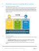
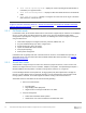
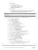
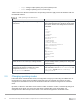
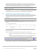
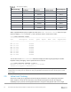
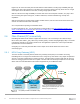
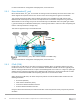
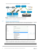
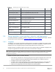
Table Of Contents
- 1 Introduction
- 2 SmartFabric Services for PowerEdge MX: An overview
- 3 SmartFabric mode requirements, guidelines, and restrictions
- 3.1 Create multi-chassis management group
- 3.2 Upstream network requirements
- 3.3 VLAN scaling guidelines
- 3.4 Configuring port speed and breakout
- 3.5 Switch slot placement for SmartFabric mode
- 3.6 Switch-to-Switch cabling
- 3.7 NIC teaming guidelines
- 3.8 Maximum Transmission Unit (MTU) behavior
- 3.9 Other restrictions and guidelines
- 4 Creating a SmartFabric
- 4.1 Physically cable MX chassis and upstream switches
- 4.2 Define VLANs
- 4.3 Create the SmartFabric
- 4.4 Configure uplink port speed or breakout, if needed
- 4.5 Create Ethernet uplink
- 4.6 Configure Fibre Channel universal ports
- 4.7 Create Fibre Channel uplinks
- 4.8 Configuring the upstream switch and connect uplink cables
- 5 Deploying a server
- 6 SmartFabric operations
- 7 Switch operations
- 8 Validating the SmartFabric deployment
- 9 SmartFabric troubleshooting
- 9.1 Troubleshooting errors encountered for port group breakout
- 9.2 Troubleshooting Spanning Tree Protocol (STP)
- 9.3 Verify VLT/vPC configuration on upstream switches
- 9.4 Discovery of FEM and compute sleds
- 9.5 Troubleshooting uplink errors
- 9.6 Troubleshooting FC/FCoE
- 9.7 SmartFabric Services – Troubleshooting commands
- 10 Uplink configuration scenarios
- 10.1 Scenario 1 - SmartFabric deployment with Dell EMC PowerSwitch Z9100-ON upstream switches
- 10.2 Scenario 2 - SmartFabric connected to Cisco Nexus 3232C switches
- 10.3 Scenario 3: Connect MX9116n FSE to Fibre Channel storage - NPIV Proxy Gateway mode
- 10.4 Scenario 4: Connect MX9116n FSE to Fibre Channel storage - FC Direct Attach
- 10.5 Scenario 5: Connect MX5108n to Fibre Channel storage - FSB
- 10.6 Scenario 6: Configure Boot from SAN
- A Hardware used in this document
- B Dell EMC Unity information
- C Additional information
- D Validated components
- E Technical resources
- F Support and feedback

15 Dell EMC PowerEdge MX SmartFabric Configuration and Troubleshooting Guide
To change a switch from SmartFabric to Full Switch mode, you must delete the fabric. At that time, all
SmartFabric GUI configuration changes are deleted except for the configurations supported by the subset of
SmartFabric CLI commands (hostname, SNMP settings, etc.) and the changes made to port interfaces,
except for admin state (shutdown/no shutdown), MTU, speed, and auto-negotiation mode.
Note: There is no CLI command to switch between operating modes. Delete the fabric to change from
SmartFabric to Full Switch mode.
The CLI command show switch-operating-mode displays the currently configured operating mode
of the switch. This information is also available on the switch landing page in the OME-M GUI.
2.4 MX9116n Fabric Switching Engine (FSE): virtual ports
A virtual port is a logical switch port that connects to a downstream server and has no physical hardware
location on the switch. Virtual ports are created when an MX9116n Fabric Switching Engine (FSE) on-boards
an MX7116n Fabric Expander Module (FEM). The onboarding process consists of discovery and
configuration.
Note: If the servers in the chassis have dual-port NICs, only QSFP28-DD port 1 on the FEM needs to be
connected. Do not connect QSFP28-DD port 2.
To verify the auto-discovered Fabric Expander Modules, enter the show discovered-expanders
command.
OS10# show discovered-expanders
Service-tag Model Type Chassis-service-tag Chassis-slot Port-group Virtual-
Slot-Id
-----------------------------------------------------------------------------------------
403RPK2 MX7116n Fabric 1 SKY003Q A2 1/1/1 71
Expander Module
If the FSE is in SmartFabric mode, the attached FEM is automatically configured and virtual ports on the
Fabric Expander Module and a virtual slot ID are created and mapped to 8x25GbE breakout interfaces in
FEM on the Fabric Engine.
An FSE in Full Switch mode automatically discovers the FEM when these conditions are met:
• The FEM is connected to the FSE by attaching a cable between the QSFP28-DD ports on both
devices
• The interface for the QSFP28-DD port-group connected to the FSE is in 8x25GbE FEM mode
• At least one blade server is inserted into the MX7000 chassis containing the FEM
Note: If the FSE is in Full Switch mode, you must manually configure the unit ID of the FEM. See the OS10
Enterprise Edition User Guide — PowerEdge MX I/O Modules for implementation.
Once the FSE discovers the FEM, it creates virtual ports by mapping each 8x25GbE FEM breakout interface
in port groups 1 to 10 to a FEM virtual port. Table 3 shows an example of this mapping.