
Users Guide
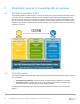
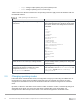
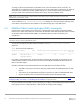
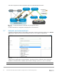
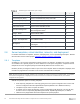
Table Of Contents
- 1 Introduction
- 2 SmartFabric Services for PowerEdge MX: An overview
- 3 SmartFabric mode requirements, guidelines, and restrictions
- 3.1 Create multi-chassis management group
- 3.2 Upstream network requirements
- 3.3 VLAN scaling guidelines
- 3.4 Configuring port speed and breakout
- 3.5 Switch slot placement for SmartFabric mode
- 3.6 Switch-to-Switch cabling
- 3.7 NIC teaming guidelines
- 3.8 Maximum Transmission Unit (MTU) behavior
- 3.9 Other restrictions and guidelines
- 4 Creating a SmartFabric
- 4.1 Physically cable MX chassis and upstream switches
- 4.2 Define VLANs
- 4.3 Create the SmartFabric
- 4.4 Configure uplink port speed or breakout, if needed
- 4.5 Create Ethernet uplink
- 4.6 Configure Fibre Channel universal ports
- 4.7 Create Fibre Channel uplinks
- 4.8 Configuring the upstream switch and connect uplink cables
- 5 Deploying a server
- 6 SmartFabric operations
- 7 Switch operations
- 8 Validating the SmartFabric deployment
- 9 SmartFabric troubleshooting
- 9.1 Troubleshooting errors encountered for port group breakout
- 9.2 Troubleshooting Spanning Tree Protocol (STP)
- 9.3 Verify VLT/vPC configuration on upstream switches
- 9.4 Discovery of FEM and compute sleds
- 9.5 Troubleshooting uplink errors
- 9.6 Troubleshooting FC/FCoE
- 9.7 SmartFabric Services – Troubleshooting commands
- 10 Uplink configuration scenarios
- 10.1 Scenario 1 - SmartFabric deployment with Dell EMC PowerSwitch Z9100-ON upstream switches
- 10.2 Scenario 2 - SmartFabric connected to Cisco Nexus 3232C switches
- 10.3 Scenario 3: Connect MX9116n FSE to Fibre Channel storage - NPIV Proxy Gateway mode
- 10.4 Scenario 4: Connect MX9116n FSE to Fibre Channel storage - FC Direct Attach
- 10.5 Scenario 5: Connect MX5108n to Fibre Channel storage - FSB
- 10.6 Scenario 6: Configure Boot from SAN
- A Hardware used in this document
- B Dell EMC Unity information
- C Additional information
- D Validated components
- E Technical resources
- F Support and feedback
14 Dell EMC PowerEdge MX SmartFabric Configuration and Troubleshooting Guide
- rstp – Configure rapid spanning-tree protocol (RSTP) mode
- vlan – Configure spanning-tree on a VLAN range
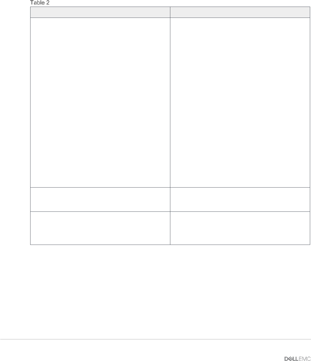
Table 2 outlines the differences between the two operating modes and apply to both the MX9116n FSE and
the MX5108n switches.
IOM operating mode differences
Full Switch mode
SmartFabric mode
Configuration changes are persistent during power
cycle events.
Only the configuration changes made using the
OS10 commands below are persistent across power
cycle events. All other CLI configuration commands
are disabled.
clock
fc alias
fc zone
fc zoneset
hostname
host-description
interface
ip nameserver
ip ssh server
ip telnet server
login concurrent-session
login statistics
logging
management route
ntp
snmp-server
tacacs-server
username
spanning-tree
vlan
All switch interfaces are assigned to VLAN 1 by
default and are in the same Layer 2 bridge domain.
Layer 2 bridging is disabled by default. Interfaces
must join a bridge domain (VLAN) before being able
to forward frames.
All configuration changes are saved in the running
configuration by default. To display the current
configuration, use the show running-
configuration command.
Verify configuration changes using feature-specific
show commands, such as show interface and
show vlan, instead of show running-
configuration.
2.3 Changing operating modes
In both Full Switch and SmartFabric modes, all configuration changes you make using the OME-M GUI are
retained when you switch modes. Dell EMC recommends using the graphical user interface for switch
configuration in SmartFabric mode and the SmartFabric OS10 CLI for switch configuration in Full Switch
mode.
By default, a switch is in Full Switch mode. When that switch is added to a fabric, it automatically changes to
SmartFabric mode. When you change from Full Switch to SmartFabric mode, all Full Switch CLI
configurations are deleted except for the subset of CLI commands supported in SmartFabric mode.