
Users Guide
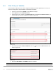
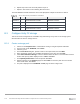

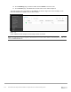
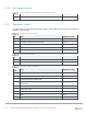
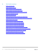

Table Of Contents
- 1 Introduction
- 2 SmartFabric Services for PowerEdge MX: An overview
- 3 SmartFabric mode requirements, guidelines, and restrictions
- 3.1 Create multi-chassis management group
- 3.2 Upstream network requirements
- 3.3 VLAN scaling guidelines
- 3.4 Configuring port speed and breakout
- 3.5 Switch slot placement for SmartFabric mode
- 3.6 Switch-to-Switch cabling
- 3.7 NIC teaming guidelines
- 3.8 Maximum Transmission Unit (MTU) behavior
- 3.9 Other restrictions and guidelines
- 4 Creating a SmartFabric
- 4.1 Physically cable MX chassis and upstream switches
- 4.2 Define VLANs
- 4.3 Create the SmartFabric
- 4.4 Configure uplink port speed or breakout, if needed
- 4.5 Create Ethernet uplink
- 4.6 Configure Fibre Channel universal ports
- 4.7 Create Fibre Channel uplinks
- 4.8 Configuring the upstream switch and connect uplink cables
- 5 Deploying a server
- 6 SmartFabric operations
- 7 Switch operations
- 8 Validating the SmartFabric deployment
- 9 SmartFabric troubleshooting
- 9.1 Troubleshooting errors encountered for port group breakout
- 9.2 Troubleshooting Spanning Tree Protocol (STP)
- 9.3 Verify VLT/vPC configuration on upstream switches
- 9.4 Discovery of FEM and compute sleds
- 9.5 Troubleshooting uplink errors
- 9.6 Troubleshooting FC/FCoE
- 9.7 SmartFabric Services – Troubleshooting commands
- 10 Uplink configuration scenarios
- 10.1 Scenario 1 - SmartFabric deployment with Dell EMC PowerSwitch Z9100-ON upstream switches
- 10.2 Scenario 2 - SmartFabric connected to Cisco Nexus 3232C switches
- 10.3 Scenario 3: Connect MX9116n FSE to Fibre Channel storage - NPIV Proxy Gateway mode
- 10.4 Scenario 4: Connect MX9116n FSE to Fibre Channel storage - FC Direct Attach
- 10.5 Scenario 5: Connect MX5108n to Fibre Channel storage - FSB
- 10.6 Scenario 6: Configure Boot from SAN
- A Hardware used in this document
- B Dell EMC Unity information
- C Additional information
- D Validated components
- E Technical resources
- F Support and feedback
123 Dell EMC PowerEdge MX SmartFabric Configuration and Troubleshooting Guide
D Validated components
D.1 Scenarios 1 and 2
The following tables include the hardware, software, and firmware used to configure and validate Scenario 1
and Scenario 2 in this document.
D.1.1 Dell EMC PowerSwitches
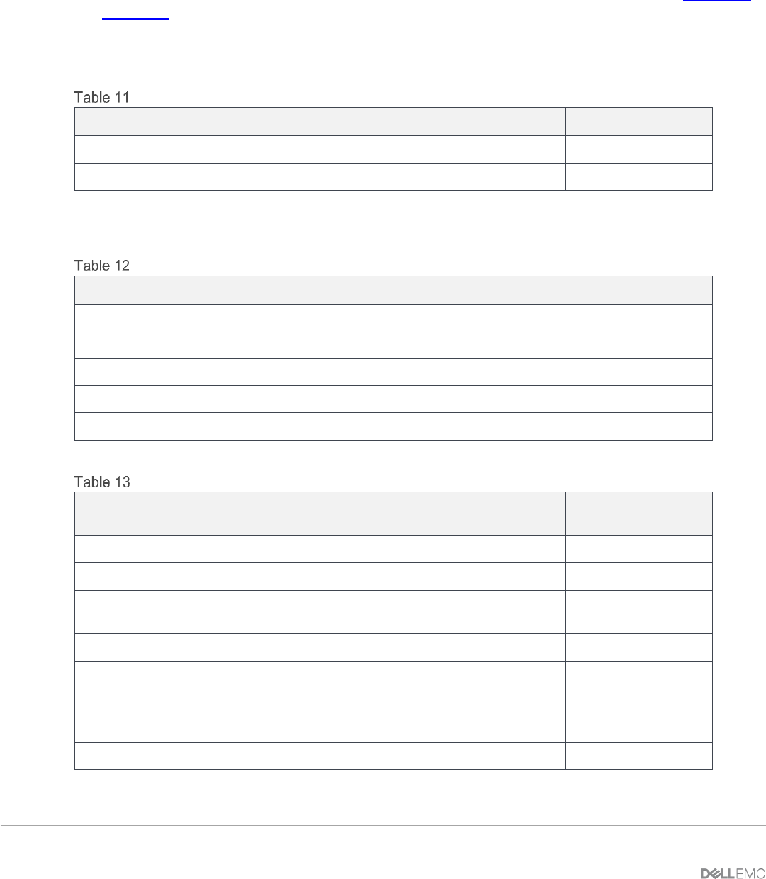
Dell EMC PowerSwitch switches and OS versions – Scenarios 1 and 2
Qty
Item
Version
2
Dell EMC PowerSwitch Z9100-ON leaf switches
10.4.0E(R3)
1
Dell EMC PowerSwitch S3048-ON OOB management switch
10.4.0E(R3P2)
D.1.2 Dell EMC PowerEdge MX7000 chassis and components
Dell EMC PowerEdge MX7000 chassis and components – Scenarios 1 and 2
Qty
Item
Version
2
Dell EMC PowerEdge MX7000 chassis
-
4
Dell EMC PowerEdge MX740c sled (2 per chassis)
-
4
Dell EMC PowerEdge M9002m modules (2 per chassis)
1.10.00
2
Dell EMC Networking MX9116n FSE (1 per chassis)
10.5.0.1
2
Dell EMC Networking MX7116n FEM (1 per chassis)
-
MX740c sled details – Scenarios 1 and 2
Qty per
sled
Item
Firmware Version
1
Intel(R) Xeon(R) Silver 4114 CPU @ 2.20GHz
-
12
16GB DDR4 DIMMs (192GB total)
-
1
Boot Optimized Storage Solution (BOSS) Controller w/ 2x240GB
SATA SSDs
2.6.13.2008
1
PERC H730P MX
25.5.3.0005
3
600GB SAS HDD
-
1
Intel(R) Ethernet 25G 2P XXV710 mezzanine card
18.5.17
-
BIOS
1.0.1
-
iDRAC with Lifecycle Controller
3.20.20.20