
Users Guide
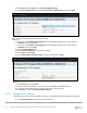
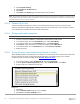
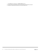
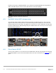
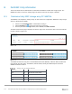
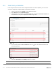
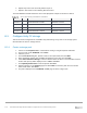

Table Of Contents
- 1 Introduction
- 2 SmartFabric Services for PowerEdge MX: An overview
- 3 SmartFabric mode requirements, guidelines, and restrictions
- 3.1 Create multi-chassis management group
- 3.2 Upstream network requirements
- 3.3 VLAN scaling guidelines
- 3.4 Configuring port speed and breakout
- 3.5 Switch slot placement for SmartFabric mode
- 3.6 Switch-to-Switch cabling
- 3.7 NIC teaming guidelines
- 3.8 Maximum Transmission Unit (MTU) behavior
- 3.9 Other restrictions and guidelines
- 4 Creating a SmartFabric
- 4.1 Physically cable MX chassis and upstream switches
- 4.2 Define VLANs
- 4.3 Create the SmartFabric
- 4.4 Configure uplink port speed or breakout, if needed
- 4.5 Create Ethernet uplink
- 4.6 Configure Fibre Channel universal ports
- 4.7 Create Fibre Channel uplinks
- 4.8 Configuring the upstream switch and connect uplink cables
- 5 Deploying a server
- 6 SmartFabric operations
- 7 Switch operations
- 8 Validating the SmartFabric deployment
- 9 SmartFabric troubleshooting
- 9.1 Troubleshooting errors encountered for port group breakout
- 9.2 Troubleshooting Spanning Tree Protocol (STP)
- 9.3 Verify VLT/vPC configuration on upstream switches
- 9.4 Discovery of FEM and compute sleds
- 9.5 Troubleshooting uplink errors
- 9.6 Troubleshooting FC/FCoE
- 9.7 SmartFabric Services – Troubleshooting commands
- 10 Uplink configuration scenarios
- 10.1 Scenario 1 - SmartFabric deployment with Dell EMC PowerSwitch Z9100-ON upstream switches
- 10.2 Scenario 2 - SmartFabric connected to Cisco Nexus 3232C switches
- 10.3 Scenario 3: Connect MX9116n FSE to Fibre Channel storage - NPIV Proxy Gateway mode
- 10.4 Scenario 4: Connect MX9116n FSE to Fibre Channel storage - FC Direct Attach
- 10.5 Scenario 5: Connect MX5108n to Fibre Channel storage - FSB
- 10.6 Scenario 6: Configure Boot from SAN
- A Hardware used in this document
- B Dell EMC Unity information
- C Additional information
- D Validated components
- E Technical resources
- F Support and feedback
118 Dell EMC PowerEdge MX SmartFabric Configuration and Troubleshooting Guide
6. Repeat steps 4 and 5 for the FCoE partition on port 2.
7. Repeat in this section for the remaining MX740c servers.
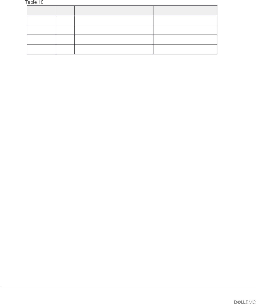
The FCoE WWPNs and MAC addresses used in this deployment example are shown in Table 10.
Server CNA FCoE port WWPNs and MACs
Server
Port
WWPN
MAC
MX740c-1
1
20:01:18:66:DA:71:50:AD
18:66:DA:71:50:AC
MX740c-1
2
20:01:18:66:DA:71:50:AF
18:66:DA:71:50:AE
MX740c-2
1
20:01:18:66:DA:77:D0:C3
18:66:DA:77:D0:C2
MX740c-2
2
20:01:18:66:DA:77:D0:C5
18:66:DA:77:D0:C4
B.3 Configure Unity FC storage
This section covers configuration of a Dell EMC Unity 500F storage array. Refer to the storage system
documentation for other FC storage devices.
B.3.1 Create a storage pool
1. Connect to the Unisphere GUI in a web browser and log in using the required credentials.
2. In the left pane under STORAGE, select Pools.
3. Click the (+) icon.
4. In the Create Pool dialog box, provide a name in the required field, then click Next.
5. Select appropriate storage tiers and RAID configuration for the pool, then click Next.
6. Under Select Amount of Storage, select the desired number of drives. The total number of drives
and the total capacity will be displayed next to Totals. Click Next
7. The Capability Profile Name section is optional. Click Next
8. Review selections on the Summary page and click Finish to create the pool. Once the Overall
status shows 100%, click Close.
9. The pool is displayed on the STORAGE > Pools page as shown in Figure 104.