
Users Guide
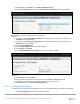
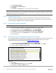
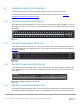
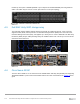
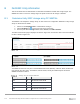
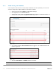
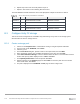

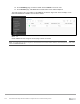
Table Of Contents
- 1 Introduction
- 2 SmartFabric Services for PowerEdge MX: An overview
- 3 SmartFabric mode requirements, guidelines, and restrictions
- 3.1 Create multi-chassis management group
- 3.2 Upstream network requirements
- 3.3 VLAN scaling guidelines
- 3.4 Configuring port speed and breakout
- 3.5 Switch slot placement for SmartFabric mode
- 3.6 Switch-to-Switch cabling
- 3.7 NIC teaming guidelines
- 3.8 Maximum Transmission Unit (MTU) behavior
- 3.9 Other restrictions and guidelines
- 4 Creating a SmartFabric
- 4.1 Physically cable MX chassis and upstream switches
- 4.2 Define VLANs
- 4.3 Create the SmartFabric
- 4.4 Configure uplink port speed or breakout, if needed
- 4.5 Create Ethernet uplink
- 4.6 Configure Fibre Channel universal ports
- 4.7 Create Fibre Channel uplinks
- 4.8 Configuring the upstream switch and connect uplink cables
- 5 Deploying a server
- 6 SmartFabric operations
- 7 Switch operations
- 8 Validating the SmartFabric deployment
- 9 SmartFabric troubleshooting
- 9.1 Troubleshooting errors encountered for port group breakout
- 9.2 Troubleshooting Spanning Tree Protocol (STP)
- 9.3 Verify VLT/vPC configuration on upstream switches
- 9.4 Discovery of FEM and compute sleds
- 9.5 Troubleshooting uplink errors
- 9.6 Troubleshooting FC/FCoE
- 9.7 SmartFabric Services – Troubleshooting commands
- 10 Uplink configuration scenarios
- 10.1 Scenario 1 - SmartFabric deployment with Dell EMC PowerSwitch Z9100-ON upstream switches
- 10.2 Scenario 2 - SmartFabric connected to Cisco Nexus 3232C switches
- 10.3 Scenario 3: Connect MX9116n FSE to Fibre Channel storage - NPIV Proxy Gateway mode
- 10.4 Scenario 4: Connect MX9116n FSE to Fibre Channel storage - FC Direct Attach
- 10.5 Scenario 5: Connect MX5108n to Fibre Channel storage - FSB
- 10.6 Scenario 6: Configure Boot from SAN
- A Hardware used in this document
- B Dell EMC Unity information
- C Additional information
- D Validated components
- E Technical resources
- F Support and feedback
116 Dell EMC PowerEdge MX SmartFabric Configuration and Troubleshooting Guide
B Dell EMC Unity information
This section shows how an administrator can determine the WWPNs of CNAs and storage targets. The
WWPNs are used to connect FC storage targets to specific servers for file storage or OS boot.
B.1 Determine Unity 500F storage array FC WWPNs
The WWPNs of FC adapters in storage arrays are also used for FC configuration. WWPNs on Unity storage
arrays are determined as follows:
1. Connect to the Unisphere GUI in a web browser and log in.
2. Click the Settings icon near the top-right corner of the page.
3. In the left pane of the Settings window, select Access, then Fibre Channel.
The Fibre Channel Ports page is displayed as shown in Figure 100. A zoomed-in view of the area inside the
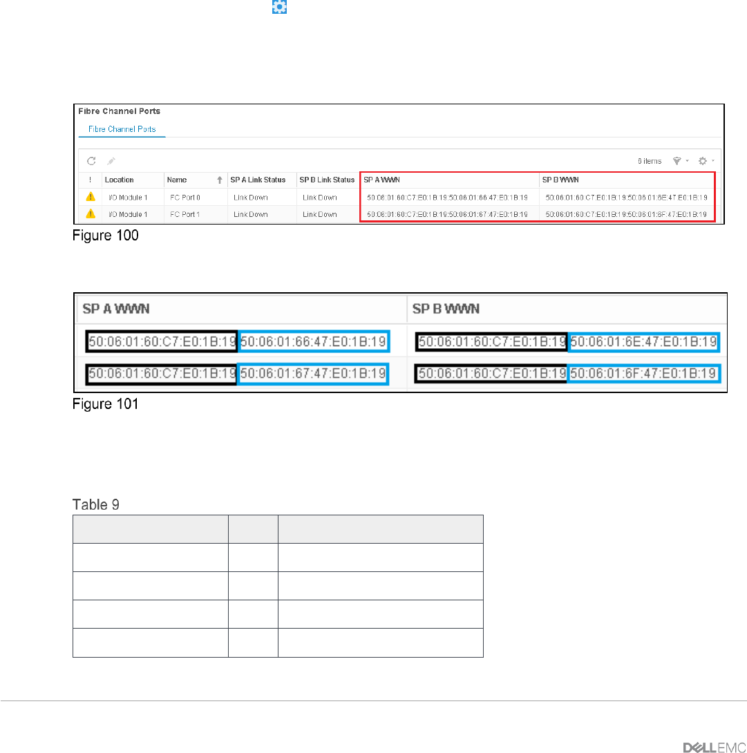
red box is shown in Figure 101.
Unisphere Fibre Channel Ports page
Zoomed-in view of SP A and SP B WWNs
Two WWNs are listed for each port. The World Wide Node Name (WWNN), outlined in black, identifies this
Unity storage array (the node). The WWPNs, outlined in blue, identify the individual ports. Record the
WWPNs as shown in Table 9.
Storage array FC adapter WWPNs
Service processor
Port
WWPN
SP A
0
50:06:01:66:47:E0:1B:19
SP A
1
50:06:01:67:47:E0:1B:19
SP B
0
50:06:01:6E:47:E0:1B:19
SP B
1
50:06:01:6F:47:E0:1B:19