
Users Guide
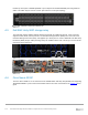
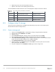

Table Of Contents
- 1 Introduction
- 2 SmartFabric Services for PowerEdge MX: An overview
- 3 SmartFabric mode requirements, guidelines, and restrictions
- 3.1 Create multi-chassis management group
- 3.2 Upstream network requirements
- 3.3 VLAN scaling guidelines
- 3.4 Configuring port speed and breakout
- 3.5 Switch slot placement for SmartFabric mode
- 3.6 Switch-to-Switch cabling
- 3.7 NIC teaming guidelines
- 3.8 Maximum Transmission Unit (MTU) behavior
- 3.9 Other restrictions and guidelines
- 4 Creating a SmartFabric
- 4.1 Physically cable MX chassis and upstream switches
- 4.2 Define VLANs
- 4.3 Create the SmartFabric
- 4.4 Configure uplink port speed or breakout, if needed
- 4.5 Create Ethernet uplink
- 4.6 Configure Fibre Channel universal ports
- 4.7 Create Fibre Channel uplinks
- 4.8 Configuring the upstream switch and connect uplink cables
- 5 Deploying a server
- 6 SmartFabric operations
- 7 Switch operations
- 8 Validating the SmartFabric deployment
- 9 SmartFabric troubleshooting
- 9.1 Troubleshooting errors encountered for port group breakout
- 9.2 Troubleshooting Spanning Tree Protocol (STP)
- 9.3 Verify VLT/vPC configuration on upstream switches
- 9.4 Discovery of FEM and compute sleds
- 9.5 Troubleshooting uplink errors
- 9.6 Troubleshooting FC/FCoE
- 9.7 SmartFabric Services – Troubleshooting commands
- 10 Uplink configuration scenarios
- 10.1 Scenario 1 - SmartFabric deployment with Dell EMC PowerSwitch Z9100-ON upstream switches
- 10.2 Scenario 2 - SmartFabric connected to Cisco Nexus 3232C switches
- 10.3 Scenario 3: Connect MX9116n FSE to Fibre Channel storage - NPIV Proxy Gateway mode
- 10.4 Scenario 4: Connect MX9116n FSE to Fibre Channel storage - FC Direct Attach
- 10.5 Scenario 5: Connect MX5108n to Fibre Channel storage - FSB
- 10.6 Scenario 6: Configure Boot from SAN
- A Hardware used in this document
- B Dell EMC Unity information
- C Additional information
- D Validated components
- E Technical resources
- F Support and feedback
114 Dell EMC PowerEdge MX SmartFabric Configuration and Troubleshooting Guide
A Hardware used in this document
This section covers the rack-mounted networking switches used in the examples in this guide.
For detailed information on Hardware components related to MX Platform please see the Dell EMC
PowerEdge MX Networking Architecture Guide.
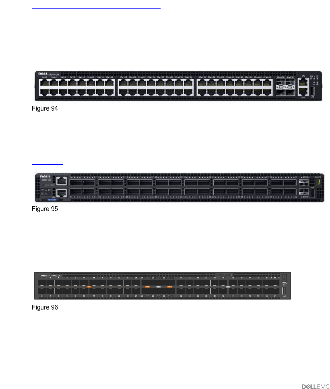
A.1 Dell EMC PowerSwitch S3048-ON
The Dell EMC PowerSwitch S3048-ON is a 1-Rack Unit (RU) switch with forty-eight 1GbE BASE-T ports and
four 10GbE SFP+ ports. In this document, one S3048-ON supports out-of-band (OOB) management traffic for
all examples.
Dell EMC PowerSwitch S3048-ON
A.2 Dell EMC PowerSwitch Z9100-ON
The Dell EMC PowerSwitch Z9100-ON is a 1-RU multilayer switch with thirty-two QSFP28 ports supporting
10/25/40/50/100GbE and two 10GbE SFP+ ports. A pair of Z9100-ON switches are used as leaf switches in
Scenario 1 in this guide.
Dell EMC PowerSwitch Z9100-ON
A.3 Dell EMC PowerSwitch S4148U-ON
The Dell EMC PowerSwitch S4148U-ON is a 1-Rack Unit (RU) switch with 48x SFP+ ports, 2x QSFP+ ports,
and 4x QSFP28 ports. In this document, two S4148U-ON supports storage traffic, and is the first of two leaf
switch options.
Stack ID
Dell EMC PowerSwitch S4148U-ON
A.4 Dell EMC PowerSwitch Z9264F-ON
The Dell EMC PowerSwitch Z9264F-ON is a 2RU fixed form-factor 100GbE multi-rate switch is optimized for
non-blocking 100GbE leaf/spine fabrics and high-density 25/50GbE in-rack server and storage connections.