
Users Guide
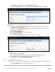
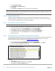
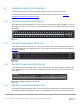
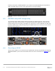
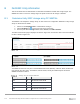
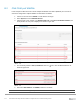

Table Of Contents
- 1 Introduction
- 2 SmartFabric Services for PowerEdge MX: An overview
- 3 SmartFabric mode requirements, guidelines, and restrictions
- 3.1 Create multi-chassis management group
- 3.2 Upstream network requirements
- 3.3 VLAN scaling guidelines
- 3.4 Configuring port speed and breakout
- 3.5 Switch slot placement for SmartFabric mode
- 3.6 Switch-to-Switch cabling
- 3.7 NIC teaming guidelines
- 3.8 Maximum Transmission Unit (MTU) behavior
- 3.9 Other restrictions and guidelines
- 4 Creating a SmartFabric
- 4.1 Physically cable MX chassis and upstream switches
- 4.2 Define VLANs
- 4.3 Create the SmartFabric
- 4.4 Configure uplink port speed or breakout, if needed
- 4.5 Create Ethernet uplink
- 4.6 Configure Fibre Channel universal ports
- 4.7 Create Fibre Channel uplinks
- 4.8 Configuring the upstream switch and connect uplink cables
- 5 Deploying a server
- 6 SmartFabric operations
- 7 Switch operations
- 8 Validating the SmartFabric deployment
- 9 SmartFabric troubleshooting
- 9.1 Troubleshooting errors encountered for port group breakout
- 9.2 Troubleshooting Spanning Tree Protocol (STP)
- 9.3 Verify VLT/vPC configuration on upstream switches
- 9.4 Discovery of FEM and compute sleds
- 9.5 Troubleshooting uplink errors
- 9.6 Troubleshooting FC/FCoE
- 9.7 SmartFabric Services – Troubleshooting commands
- 10 Uplink configuration scenarios
- 10.1 Scenario 1 - SmartFabric deployment with Dell EMC PowerSwitch Z9100-ON upstream switches
- 10.2 Scenario 2 - SmartFabric connected to Cisco Nexus 3232C switches
- 10.3 Scenario 3: Connect MX9116n FSE to Fibre Channel storage - NPIV Proxy Gateway mode
- 10.4 Scenario 4: Connect MX9116n FSE to Fibre Channel storage - FC Direct Attach
- 10.5 Scenario 5: Connect MX5108n to Fibre Channel storage - FSB
- 10.6 Scenario 6: Configure Boot from SAN
- A Hardware used in this document
- B Dell EMC Unity information
- C Additional information
- D Validated components
- E Technical resources
- F Support and feedback
112 Dell EMC PowerEdge MX SmartFabric Configuration and Troubleshooting Guide
2. Select Network Settings.
3. Click Disable for all PXE Devices.
4. Click Back.
5. Click Finish, click Finish again, then select Yes to exit and reboot.
Note: As previously documented, this server configuration may be used to generate a template to deploy to other
servers with identical hardware. When a template is not used, repeat the steps in this chapter for each MX server
sled that requires access to the FC storage.
10.6.3 Connect FCoE LUN
The server should be provisioned to connect to an FCoE boot LUN before moving on to Section 10.6.4.
Follow the procedures in Appendix B to configure and connect to an FCoE LUN. Once connected, continue
to the steps below to complete the Boot from SAN configuration.
10.6.4 Set up install media connection
Note: The steps in this section were completed using the iDRAC Java Virtual Console.
1. Connect to the server’s iDRAC in a web browser and launch the virtual console.
2. In the virtual console, from the Virtual Media menu, select Virtual Media.
3. In the virtual console, from the Virtual Media menu, select Map CD/DVD.
4. Click Browse to find the location of the OS install media then click Map Device.
5. In the virtual console, from the Next Boot menu, select Lifecycle Controller.
6. Reboot the server.
10.6.5 Set up OS driver install media using Lifecycle Controller
Some Operating System’s install media do not contain the necessary FCoE drivers to boot from a FCoE LUN.
Use this procedure to create an internal OS install media device. For VMware ESXi, refer to the Dell
customized media instructions provided on the Dell EMC Support website.
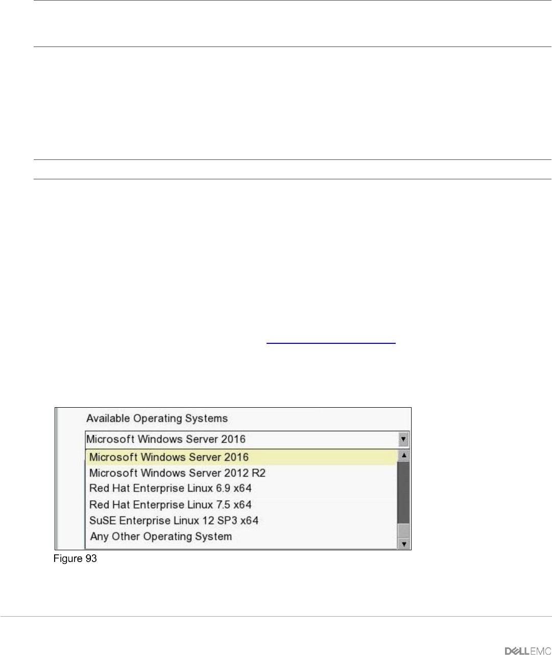
1. In Lifecycle Controller, select OS Deployment, then select Deploy OS.
2. From the Select an Operating System screen, verify that Boot mode is set to UEFI.
3. Select an OS to be installed to the boot LUN.
Lifecycle Controller OS deployment menu
4. Click Next.
5. Click the Manual Install check box, then click Next.
6. Click Next on the Insert OS Media screen.