
Users Guide

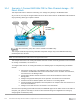

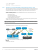
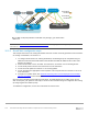
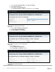
Table Of Contents
- 1 Introduction
- 2 SmartFabric Services for PowerEdge MX: An overview
- 3 SmartFabric mode requirements, guidelines, and restrictions
- 3.1 Create multi-chassis management group
- 3.2 Upstream network requirements
- 3.3 VLAN scaling guidelines
- 3.4 Configuring port speed and breakout
- 3.5 Switch slot placement for SmartFabric mode
- 3.6 Switch-to-Switch cabling
- 3.7 NIC teaming guidelines
- 3.8 Maximum Transmission Unit (MTU) behavior
- 3.9 Other restrictions and guidelines
- 4 Creating a SmartFabric
- 4.1 Physically cable MX chassis and upstream switches
- 4.2 Define VLANs
- 4.3 Create the SmartFabric
- 4.4 Configure uplink port speed or breakout, if needed
- 4.5 Create Ethernet uplink
- 4.6 Configure Fibre Channel universal ports
- 4.7 Create Fibre Channel uplinks
- 4.8 Configuring the upstream switch and connect uplink cables
- 5 Deploying a server
- 6 SmartFabric operations
- 7 Switch operations
- 8 Validating the SmartFabric deployment
- 9 SmartFabric troubleshooting
- 9.1 Troubleshooting errors encountered for port group breakout
- 9.2 Troubleshooting Spanning Tree Protocol (STP)
- 9.3 Verify VLT/vPC configuration on upstream switches
- 9.4 Discovery of FEM and compute sleds
- 9.5 Troubleshooting uplink errors
- 9.6 Troubleshooting FC/FCoE
- 9.7 SmartFabric Services – Troubleshooting commands
- 10 Uplink configuration scenarios
- 10.1 Scenario 1 - SmartFabric deployment with Dell EMC PowerSwitch Z9100-ON upstream switches
- 10.2 Scenario 2 - SmartFabric connected to Cisco Nexus 3232C switches
- 10.3 Scenario 3: Connect MX9116n FSE to Fibre Channel storage - NPIV Proxy Gateway mode
- 10.4 Scenario 4: Connect MX9116n FSE to Fibre Channel storage - FC Direct Attach
- 10.5 Scenario 5: Connect MX5108n to Fibre Channel storage - FSB
- 10.6 Scenario 6: Configure Boot from SAN
- A Hardware used in this document
- B Dell EMC Unity information
- C Additional information
- D Validated components
- E Technical resources
- F Support and feedback
109 Dell EMC PowerEdge MX SmartFabric Configuration and Troubleshooting Guide
10.6 Scenario 6: Configure Boot from SAN
The host OS of MX Server can boot from a remote FC storage array utilizing the IOMs. Booting to an OS
through FC direct attach (F_port), FC (NPG), and FCoE (FSB) scenarios are supported.
FC storage
MX9116n
Boot from SAN
(3 methods)
MX7000
Server
Server
FC (NPG)
MX5108n
MX7000
Server
Server
Direct Attached (F_port)
FCoE (FSB)
MX9116n
MX7000
Server
Server
Boot from SAN
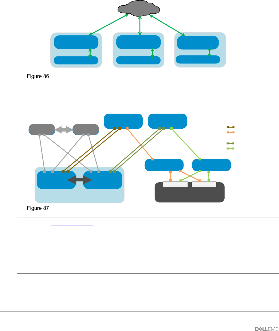
Figure 87 shows the example topology used in this chapter to demonstrate Boot from SAN. The required
steps are provided to configure NIC partitioning, system BIOS, an FCoE LUN, and an OS install media device
required for Boot from SAN.
S4148u
(NPG mode)
S4148u
(NPG mode)
Unity 500F
MX5108n
FSB mode
(Leaf 2)
MX5108n
FSB mode
(Leaf 1)
VLT
MX7000 chassis
ToR switch 2
ToR switch 1
FC SwitchFC Switch
Unity 500F
Unity 500F
Controller A Controller B
VLT
FC SAN A
FC SAN B
FCoE SAN A
FCoE SAN B
FCoE Boot from SAN
Note: See the OS10 User Guide document for configuring NPG mode globally on the S4148U-ON switches.
10.6.1 Configure NIC Boot Device
In this section, each QLogic CNA port is partitioned into one Ethernet and one FCoE partition.
Note: This is only done on CNA ports that carry converged traffic. In this example, these are the two 25GbE
QLogic CNA ports on each server that attach to the switches internally through an orthogonal connection.
1. Connect to the server's iDRAC in a web browser and launch the virtual console.
2. In the virtual console, select BIOS Setup from the Next Boot menu.
3. Reboot the server.