
Users Guide

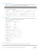
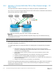
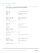

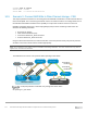
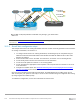
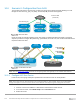
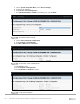
Table Of Contents
- 1 Introduction
- 2 SmartFabric Services for PowerEdge MX: An overview
- 3 SmartFabric mode requirements, guidelines, and restrictions
- 3.1 Create multi-chassis management group
- 3.2 Upstream network requirements
- 3.3 VLAN scaling guidelines
- 3.4 Configuring port speed and breakout
- 3.5 Switch slot placement for SmartFabric mode
- 3.6 Switch-to-Switch cabling
- 3.7 NIC teaming guidelines
- 3.8 Maximum Transmission Unit (MTU) behavior
- 3.9 Other restrictions and guidelines
- 4 Creating a SmartFabric
- 4.1 Physically cable MX chassis and upstream switches
- 4.2 Define VLANs
- 4.3 Create the SmartFabric
- 4.4 Configure uplink port speed or breakout, if needed
- 4.5 Create Ethernet uplink
- 4.6 Configure Fibre Channel universal ports
- 4.7 Create Fibre Channel uplinks
- 4.8 Configuring the upstream switch and connect uplink cables
- 5 Deploying a server
- 6 SmartFabric operations
- 7 Switch operations
- 8 Validating the SmartFabric deployment
- 9 SmartFabric troubleshooting
- 9.1 Troubleshooting errors encountered for port group breakout
- 9.2 Troubleshooting Spanning Tree Protocol (STP)
- 9.3 Verify VLT/vPC configuration on upstream switches
- 9.4 Discovery of FEM and compute sleds
- 9.5 Troubleshooting uplink errors
- 9.6 Troubleshooting FC/FCoE
- 9.7 SmartFabric Services – Troubleshooting commands
- 10 Uplink configuration scenarios
- 10.1 Scenario 1 - SmartFabric deployment with Dell EMC PowerSwitch Z9100-ON upstream switches
- 10.2 Scenario 2 - SmartFabric connected to Cisco Nexus 3232C switches
- 10.3 Scenario 3: Connect MX9116n FSE to Fibre Channel storage - NPIV Proxy Gateway mode
- 10.4 Scenario 4: Connect MX9116n FSE to Fibre Channel storage - FC Direct Attach
- 10.5 Scenario 5: Connect MX5108n to Fibre Channel storage - FSB
- 10.6 Scenario 6: Configure Boot from SAN
- A Hardware used in this document
- B Dell EMC Unity information
- C Additional information
- D Validated components
- E Technical resources
- F Support and feedback

101 Dell EMC PowerEdge MX SmartFabric Configuration and Troubleshooting Guide
10.3.1 Configuration validation
10.3.1.1 show fc ns switch
The show fc ns switch command shows all device ports logged into the fabric. In this deployment, four
ports are logged in to each switch: two storage ports and two CNA ports.
C140A1# show fc ns switch
Total number of devices = 3
Switch Name 10:00:20:04:0f:00:cd:1e
Domain Id 1
Switch Port fibrechannel1/1/44:1
FC-Id 01:00:00
Port Name 50:06:01:61:47:e4:1b:19
Node Name 50:06:01:60:c7:e0:1b:19
Class of Service 8
Symbolic Port Name UNITY::::SPA13::FC::::::
Symbolic Node Name UNITY::::SPA::FC::::::
Port Type N_PORT
Registered with NameServer Yes
Registered for SCN Yes
Switch Name 10:00:20:04:0f:00:cd:1e
Domain Id 1
Switch Port ethernet1/71/1
FC-Id 01:01:00
Port Name 20:01:06:c3:f9:a4:cd:03
Node Name 20:00:06:c3:f9:a4:cd:03
Class of Service 8
Symbolic Port Name
Symbolic Node Name
Port Type N_PORT
Registered with NameServer Yes
Registered for SCN Yes
Switch Name 10:00:20:04:0f:00:cd:1e
Domain Id 1
Switch Port ethernet1/1/1
FC-Id 01:02:00
Port Name 20:01:f4:e9:d4:73:d0:0c
Node Name 20:00:f4:e9:d4:73:d0:0c
Class of Service 8
Symbolic Port Name QLogic qedf v8.24.8.0
Symbolic Node Name QLogic qedf v8.24.8.0
Port Type N_PORT
Registered with NameServer Yes
Registered for SCN Yes