Dell EMC PowerEdge MX SmartFabric Configuration and Troubleshooting Guide Abstract This document provides the steps for configuring and troubleshooting the Dell EMC PowerEdge MX networking switches in SmartFabric mode. It includes examples for ethernet connections to Dell EMC Networking, Cisco Nexus, and Fibre Channel networks. This document replaces the Dell EMC PowerEdge MX SmartFabric Mode Deployment Guide, which is now deprecated.
Revisions Date Description September 2019 OpenManage Enterprise-Modular 1.10.00 and SmartFabric OS10.5.0.1 updates, Fibre Channel connectivity, additional troubleshooting information May 2019 Initial Release The information in this publication is provided “as is.” Dell Inc. makes no representations or warranties of any kind with respect to the information in this publication, and specifically disclaims implied warranties of merchantability or fitness for a particular purpose.
Table of contents Revisions.............................................................................................................................................................................2 1 2 Introduction ...................................................................................................................................................................8 1.1 Typographical conventions ...............................................................................................
3.8 Maximum Transmission Unit (MTU) behavior ..................................................................................................28 3.9 Other restrictions and guidelines ......................................................................................................................28 Creating a SmartFabric ..............................................................................................................................................30 4.
7.1.1 Switch overview ................................................................................................................................................56 7.1.2 Hardware tab ....................................................................................................................................................58 7.1.3 Firmware tab .....................................................................................................................................................59 7.
9.7 SmartFabric Services – Troubleshooting commands.......................................................................................85 9.7.1 show smartfabric personality ............................................................................................................................85 9.7.2 show smartfabric cluster ...................................................................................................................................85 9.7.3 show smartfabric cluster member.....
B.1 Determine Unity 500F storage array FC WWPNs ..........................................................................................116 B.2 CNA FCoE port WWPNs ................................................................................................................................117 B.3 Configure Unity FC storage ............................................................................................................................118 B.3.1 Create a storage pool .....................
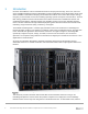
1 Introduction Our vision at Dell EMC is to be the essential infrastructure company from the edge, to the core, and to the cloud. Dell EMC Networking ensures modernization for today’s applications and for the emerging cloud-native world. Dell EMC is committed to disrupting the fundamental economics of the market with an open strategy that gives you the freedom of choice for networking operating systems and top-tier merchant silicon.
operate as a Layer 2 I/O aggregation fabric and are managed through the Open Manage Enterprise - Modular (OME-M) graphical user interface or console.
1.1 Typographical conventions The CLI and GUI examples in this document use the following conventions: 1.2 Monospace Text CLI examples Underlined Monospace Text CLI examples that wrap the page Italic Monospace Text Variables in CLI examples Bold Monospace Text Commands entered at the CLI prompt, or to highlight information in CLI output Bold text UI elements and information entered in the GUI Attachments This document in .pdf format includes one or more file attachments.
2 SmartFabric Services for PowerEdge MX: An overview 2.1 Dell EMC SmartFabric OS10 The networking market is transitioning from a closed, proprietary stack to open hardware supporting a variety of operating systems. Dell EMC SmartFabric OS10 is designed to allow multi-layered disaggregation of the network functionality.
• show switch-operating-mode – displays the current operating mode (SmartFabric or Full Switch) of a supported switch • show discovered-expanders – displays the MX7116n FEMs attached to the MX9116n FSEs • show unit-provision – displays or configures the unit ID and service tag of a MX7116n FEM attached to a MX9116n FSE Note: For more information, see the SmartFabric OS10 User Guide for PowerEdge MX I/O Modules on the Support for Dell EMC Networking MX9116n - Manuals and documents and Support for Dell
3. Fabric automation • • • • Physical topology compliance Server networking managed via templates Automated QoS assignment per VLAN Automated storage networking 4.
- rstp – Configure rapid spanning-tree protocol (RSTP) mode vlan – Configure spanning-tree on a VLAN range Table 2 outlines the differences between the two operating modes and apply to both the MX9116n FSE and the MX5108n switches. IOM operating mode differences Full Switch mode SmartFabric mode Configuration changes are persistent during power cycle events. Only the configuration changes made using the OS10 commands below are persistent across power cycle events.
To change a switch from SmartFabric to Full Switch mode, you must delete the fabric. At that time, all SmartFabric GUI configuration changes are deleted except for the configurations supported by the subset of SmartFabric CLI commands (hostname, SNMP settings, etc.) and the changes made to port interfaces, except for admin state (shutdown/no shutdown), MTU, speed, and auto-negotiation mode. Note: There is no CLI command to switch between operating modes.
Virtual port mapping FEM service tag FSE QSFP28-DD port group 12AB3456 portgroup1/1/1 FSE 25G interfaces FEM unit ID (virtual slot ID) 1/1/17:1 71 FEM virtual ports 1/71/1 1/1/17:2 1/71/2 1/1/17:3 1/71/3 1/1/17:4 1/71/4 1/1/18:1 1/71/5 1/1/18:2 1/71/6 1/1/18:3 1/71/7 1/1/18:4 1/71/8 When a QSFP28-DD port group is mapped to a FEM, in the show interface status output, the eight interfaces display dormant instead of up until a virtual port starts to transmit server traffic: OS10# show in
logical unit, the control and data plane of both switches remain isolated, ensuring high availability and high resilience for all its connected devices. This differs from the legacy stacking concept, where there is a single control plane across all switches in the stack, creating a single point of failure.
For more information on configuration and deployment, see Section 10.3. 2.6.2 Direct Attached (F_port) Direct Attached mode, or F_port, is used when FC storage needs to be directly connected to the switch. The switch supports the required services such as name server and zoning that are typical of FC switches. This example demonstrates Fibre Channel directly attaching to the Dell EMC Unity 500F storage array.
This mode is supported on both the MX9116n FSE and the MX5108n Ethernet Switch. ToR switch 1 VLT S4148U-ON S4148U-ON (NPG mode) (NPG mode) ToR switch 2 FCoE SAN A FC SAN A FCoE SAN B FC SAN B FC Switch MX5108n FSB mode (Leaf 1) VLT FC Switch MX5108n FSB mode (Leaf 2) MX7000 chassis Controller A Controller B Unity 500F UnityUnity 500F 500F FCoE (FSB) Network to Dell EMC Unity through NPG switch For more information on configuration and deployment, see Section 10.5. 2.
Network types and default QoS settings 2.
2.8.2 Virtual identities and identity pools Some of the attributes included in a template are referred to as identity attributes. Identity attributes identify a device and distinguish it from all other devices on the network. Since identity attributes must uniquely identify a device, it is imperative that each device has a unique network identity. Otherwise, devices won’t be able to communicate with each other over the network.
3 SmartFabric mode requirements, guidelines, and restrictions Before deploying a SmartFabric, ensure that the following requirements, guidelines, and restrictions are followed. Failure to do so may impact your network. 3.1 Create multi-chassis management group For a scalable fabric that uses more than one MX chassis, the chassis must be in a Multi-Chassis Management (MCM) Group.
3.2.2 Spanning Tree Protocol By default, SmartFabric OS10 uses Rapid per-VLAN Spanning Tree Plus (RPVST+) across all switching platforms including PowerEdge MX networking IOMs. SmartFabric OS10 also supports RSTP. Note: Dell EMC recommends using RSTP instead of RPVST+ when more than 64 VLANs are required in a fabric to avoid performance problems. Caution should be taken when connecting an RPVST+ to an existing RSTP environment.
Recommended maximum number of VLANs in SmartFabric mode OS10 Version 10.5.0.1 10.4.0.R3S 10.4.0.R4S 3.
IOM placement – 2 x MX9116n in different chassis 3.5.2 Two MX5108n Ethernet switches in the same chassis The MX5108n Ethernet Switch is only supported in single chassis configurations, with the switches in either slots A1/A2 or slots B1/B2. A SmartFabric cannot include a switch in Fabric A and a switch in Fabric B.
3.5.3 Two MX9116n Fabric Switching Engines or FSEs in the same chassis This placement should only be used in environments with a single chassis, with the switches in either slots A1/A2 or slots B1/B2. A SmartFabric cannot include a switch in Fabric A and a switch in Fabric B. IOM placement – 2 x MX9116n in the same chassis 3.6 Switch-to-Switch cabling When operating in SmartFabric mode, each switch pair runs a VLT interconnect (VLTi) between them.
3.6.1 VLT backup link A pair of cables is used to provide redundancy for the VLTi link. A third redundancy mechanism, a VLT backup link is automatically created when the SmartFabric is created. This link exchanges VLT heartbeat information between the two switches to avoid a split-brain scenario should the external VLTi links go down. Based on the node liveliness information, the VLT LAG/port is in up state in the primary VLT peer and in down state in the secondary VLT peer.
2. Microsoft Windows 2016, see Instructions Refer to the network adapter or operating system documentation for detailed NIC teaming instructions. Note: If using VMware ESXi and LACP, it is recommended to use VMware ESXi 6.7.0 Update 2. Table 6 shows the options that MX Platform provides for NIC Teaming. NIC Teaming Options on MX Platform No Teaming No NIC Bonding/Teaming or Switch Independent Teaming LACP Teaming LACP (Also called 802.3ad or Dynamic Link Aggregation) Other Other (Not recommended.
6. In SmartFabric mode, although you can use the CLI to create VLANs 1 to 4000 and 4021 to 4094, you cannot assign interfaces to them. For this reason, do not use the CLI to create VLANs in SmartFabric mode. 7. VLAN 1 is automatically created as the Default/Native VLAN, but it is not required to be used. See Section 4.2 for more information. 8. When using LACP NIC teaming, the LACP timer must be set to slow. 9.
4 Creating a SmartFabric The general steps required to create a SmartFabric are: 1. 2. 3. 4. 5. 6. Physically cable the MX chassis and upstream switches. Define the VLANs. Create the SmartFabric. If needed, configure uplink port speed and breakout. Create the Ethernet uplink. Configure the upstream switch and connect uplink cables. These steps make the following assumptions: • • • All MX7000 chassis and management modules are cabled correctly and in a Multi-Chassis Management group.
• • • Enter the VLAN number in the VLAN ID box. In this example, 10 was entered. From the Network Type list, select the desired network type. In this example, General Purpose (Bronze) was used. Click Finish. Defined VLAN list Figure 13 shows VLAN 1 and VLAN 10 after being created using the steps above. 4.2.1 Define VLANs for FCoE Note: Define VLANs for FCoE, if implementing Fibre Channel configurations as per requirement. A standard Ethernet uplink carries assigned VLANs on all physical uplinks.
Defined VLAN list Note: To create VLANs for FCoE, From the Network Type list, select Storage – FCoE, and then click Finish. VLANs to be used for FCoE must be configured as the Storage – FCoE network type. 4.3 Create the SmartFabric To create a SmartFabric using the OME-M console, perform the following steps: 1. 2. 3. 4. Open the OME-M console. From the navigation menu, click Devices > Fabric. In the Fabric pane, click Add Fabric.
SmartFabric deployment design window The SmartFabric deploys. This process can take several minutes to complete. During this time all related switches will be rebooted, and the operating mode changed to SmartFabric mode. Note: After the fabric is created, the fabric health will be critical until at least one uplink is created. Figure 16 shows the new SmartFabric object and some basic information about the fabric. SmartFabric post-deployment without defined uplinks 4.
Note: Prior to choosing the breakout type, you must set the Breakout Type to HardwareDefault and then set the desired configuration. If the desired breakout type is selected prior to setting HardwareDefault, an error will occur. 6. Choose Configure Breakout. In the Configure Breakout dialog box, select HardwareDefault. 7. Click Finish. First set the breakout type to HardwareDefault 8. Once the job is completed, choose Configure Breakout.
3. 4. 5. 6. Click on the fabric name. In this example, SmartFabric is selected. In the Fabric Details pane, click Uplinks. Click on the Add Uplinks button. In the Add Uplink window complete the following: • Enter a name for the uplink in the Name box. In this example, Uplink01 is entered. • Optionally, enter a description in the Description box. • From the Uplink Type list, select the desired type of uplink. In this example, Ethernet is selected. • Click Next.
Note: VLAN1 will be assigned to Untagged Network by default. 4.6 Configure Fibre Channel universal ports Note: Configure Fibre Channel universal ports, if implementing Fibre Channel configurations as per requirement. On the MX9116n FSE, port-group 1/1/15 and 1/1/16 are universal ports capable of connecting to FC devices at a variety of speeds depending on the optic being used. In this example, we are configuring the universal port speed as 4x16G FC.
5. From the Add Uplinks window, use the information in Table 8 to enter an uplink name in the Name box. 6. Optionally, enter a description in the Description box. 7. From the Uplink Type list, select Type, then click Next. In this example, FCoE as Uplink type is selected. Choose Uplink type as per your configuration from FC Gateway, FC Direct Attach or FCoE options. 8. From the Switch Ports list, select the FC ports as defined in Table 8. Select appropriate port for the connected uplink. 9.
5 Deploying a server Before beginning, ensure that all server firmware, especially the NIC/CNA, has been updated to the latest version. 5.1 Server preparation The examples in this guide use a reference server of a Dell EMC PowerEdge MX740c compute sled with QLogic (model QL41262HMKR) Converged Network Adapters (CNAs) installed. CNAs are required to achieve FCoE connectivity.
Note: This is only done on CNA ports that carry converged traffic. In this example, these are the two 25GbE QLogic CNA ports on each server that attach to the fabric internally. If the system is already in System Setup from the previous section, skip to step 4. 1. 2. 3. 4. 5. 6. 7. 8. Using a web browser, connect to the iDRAC server and launch the Virtual Console. From the Virtual Console, click Next Boot menu then select BIOS Setup. Select the option to reboot the server.
16. Select the second CNA port and repeat steps in this section for port 2 17. After configuring port 2, click Finish, then Finish. 18. Click Yes to exit and reboot. 5.1.3 Configure other server settings Depending on application and infrastructure requirements, also configure other server’s settings such as BIOS, RAID, iDRAC as appropriate. 5.
Create Template dialog box 5. 6. 7. 8. Optionally, enter a description in the Description box, then click Next. In the Device Selection section, click Select Device. From the Select Devices window, choose the server previously configured, then click Finish. From the Elements to Clone list, select all the elements, and then click Finish. Select the elements to clone A job starts and the new server template displays on the list. When complete, the Completed successfully status displays.
5.3 Create identity pools Dell EMC recommends the use of identity pools. Virtual identity pools are used in conjunction with server templates to automate network onboarding of compute sleds. Follow these steps to create an ID pool: 1. 2. 3. 4. 5. 6. 7. 8. 9. 10. 11. 12. Open the OME-M console. From the navigation menu, click Configure, then click Identity Pools. In the Network panel, click Create. The Create Identity Pool window displays. Type Ethernet CNA into the Pool Name box.
• • • • The NIC teaming option can be selected from No Teaming, LACP teaming and Other as mentioned in Table 6. For both ports, from the Untagged Network list, select the untagged VLAN. In this example, VLAN0001 is selected. For both ports, from the Tagged Network list, select the tagged VLAN. In this example, VLAN0010 is selected. Click Finish. Figure 25 shows the associated networks for the server template. Server template network settings 5.
Server Template Network Settings 5.6 Deploy a server template To deploy the server template, complete the following steps: 1. From the Deploy pane, select the template to be deployed. In this example, MX740c with FCOE CNA server template is selected. 2. Click Deploy Template. 3. In the Deploy Template window, complete the following: • • • Click the Select button to choose which slots or compute sleds to deploy the template to. Select the Do not forcefully reboot the host OS option. Click Next.
Job displaying Deployment of Server Template 45 Dell EMC PowerEdge MX SmartFabric Configuration and Troubleshooting Guide
6 SmartFabric operations 6.1 Viewing the fabric A SmartFabric is viewed using OME-M. The green check mark adjacent to the fabric name informs that the status of the fabric is healthy. In this example, the fabric created is named Fabric01. 1. Open the OME-M console. 2. From the navigation menu, click Devices > Fabric. 3. To view the Fabric components, select the fabric. This can also be achieved by clicking the View Details button the right.
Switches are the I/O Modules that are part of the fabric. In this example, the fabric has two MX9116n switches. Note: Fabric Expander Modules are transparent and therefore do not appear on the Fabric Details page. Switches Servers are the compute sleds that are part of the fabric. In this example, two PowerEdge MX740c compute sleds are part of the fabric. Servers ISL Links are the VLT interconnects between the two switches.
ISL Links 6.2 Editing the fabric A fabric has four components: • • • • Uplinks Switches Servers ISL Links Editing the fabric discussed in this section includes editing the fabric name and description. To edit the name of the fabric that was created, follow the steps below: 1. Open the OME-M console. 2. From the navigation menu, click Devices > Fabric. 3. On the right, Click the Edit button.
4. In the Edit Fabric dialog box, change the name and description as desired. Click Finish. Edit Fabric dialog box 6.3 Editing uplinks Editing the uplinks on the created fabric is done using the following steps: 1. 2. 3. 4. 5. Open the OME-M console. From the navigation menu, click Devices > Fabric. Select the fabric. Select the Uplink to edit and click Edit. In this example, Uplink1 is selected. In the Edit Uplink dialog box, modify the Name and Description as desired.
7. Edit the uplink ports on the MX switches that connects to the upstream switches. In this example, ports 41 and 42 on the MX9116n switches that connects to upstream switches are displayed. Note: Care should be taken to modify the uplink ports on both MX switches. Select the IOM to display the respective uplink switch ports. Edit uplink ports and VLAN networks 8. If desired, modify the tagged and untagged VLANs. 9. Click Finish. 6.
Add/remove VLANs 5. Choose the desired server. In this example PowerEdge MX740C with service tag 8XQP0T2 is selected. 6. Choose Edit Networks. 7. Choose NIC teaming from LACP, No Teaming and Other options. 8. Modify the VLAN selections as required by defining the tagged and untagged VLANs. 9. Select VLANs on Tagged and Untagged Network for each Mezzanine card port. 10. Click Save. Modify VLANs Note: At this time, only one server can be selected at a time in the GUI. 6.
A FC Alias is a human defined name that references a WWN. This allows users to refer to those devices by the easy to remember alias instead of the long WWN. In this example, aliases for two MX740c compute sleds and a Dell EMC Unity storage array is defined. The WWNs for the servers are obtained via OME-M console.
6.6 member mx740c-2p1zone exit member mx740c-2p2zone exit write memory write memory Connecting non-MX Ethernet Devices to the fabric As of SmartFabric OS10.5.0.1 and OME-M 1.10.00, PowerEdge MX Ethernet switches allow the connection of non-MX devices such as rack servers to the fabric as long as that device provides a physical interface supported by the switch. Once connected, VLANs must be assigned to each port that the device is connected to.
Note: Any configuration not completed by the OME-M console is lost when switching between IOM operating modes. 6.8 Module replacement process in SmartFabric Dell EMC PowerEdge MX platform gives you an option to replace the I/O Modules in a SmartFabric mode in case of any errors or failures. MX9116n FSE and MX5108n can be replaced with another same type of I/O Module. In case of errors or failures, replace the old IOM with the new IOM using Linux command.
The console displays the following output on Member IOM: admin@MX9116N-A1:/opt/dell/os10/bin$sfs_master_details.py Master IP Address: fde1:53ba:e9a0:de14:2204:fff:fe01:cd90 • 6.8.3 To login to master IOM from member IOM, run ssh admin@Master IP Address command. Execute process of Module Replacement with Linux command To replace an old IOM with the new IOM and on board the new IOM, run the following command in the same bin directory on SmartFabric OS10.
7 Switch operations PowerEdge MX switches can be managed using the OME-M console. From the Switch Management page, you can view activity, health, and alerts, as well as perform operations such as power control, firmware update, and port configuration. Some of these operations can also be performed in Full Switch mode. 7.1 Switch management page overview To get to the switch management page, follow these steps: 1. Open the OME-M console 2. From the navigation menu, click Devices > I/O Modules. 3.
• Environment The Power Control drop-down button provides three options: • • • Power Off: Turns off the IOM Power Cycle: Power cycles the IOM System Reseat: Initiates a cold reboot of the IOM Power Control button The Blink LED drop down button provides an option to turn on or turn off the ID LED on the IOM. To turn on the ID LED, choose: • Blink LED > Turn On This activates a blinking blue LED and provides easy identification.
7.1.
7.1.3 Firmware tab The Firmware tab provides options to manage the firmware on the IOM. The Dell Update Package (DUP) file is used to update the firmware of the IOM. Firmware Tab 7.1.4 Alerts tab The Alert tab provides information on alerts and notifies the administrator. The advanced filter option can be leveraged to quickly filter out alerts.
7.1.5 Settings tab The Settings tab provides options to configure the following settings for the IOMs: • • • • Network Management Monitoring Advanced Settings Settings Tab The Network option includes configuring IPv4, IPv6, DNS Server and Management VLAN settings.
The Management option includes setting the hostname and linuxadmin password. Note: Although the GUI has the field name listed as Root Password, it denotes the linuxadmin password. For logging on to the CLI of the MX switch, use default credentials with username as admin and password as admin. Management Settings Monitoring provides options for SNMP settings. Monitoring Settings The Advanced Settings tab offers the option for time configuration replication and alert replication.
Advanced Settings 7.2 Configuring Ethernet ports The MX switches can be accessed using the OME-M console. Various operations such as port breakout, altering the MTU size, enabling/disabling auto negotiation etc. Follow the below steps to gain insight into modifying various entities. Note: In SmartFabric mode, configuring interfaces via the CLI should not be performed. Use the OME-Modular GUI 1. From the switch management page, choose Hardware > Port Information.
Port information 2. To configure MTU, select the port listed under the respective port-group. 3. Click Configure MTU. Enter MTU size in bytes. 4. Click Finish. Configure MTU 5. To configure Auto Negotiation, select the port listed under the respective port-group. Click Toggle AutoNeg. This will change the Auto Negotiation of the port to Disabled/Enabled. Click Finish. Enable/Disable Auto Negotiation 6.
Toggle Admin State 7.3 Upgrade Dell EMC SmartFabric OS10 Upgrading the IOMs in the fabric can be done using the OME-M console. The upgrade is carried out using a Dell Update Package (DUP). A DUP is a self-contained package format that updates a single element on a system. Using DUPs, you can update a wide range of system components simultaneously and apply scripts to similar sets of Dell systems to levels. The OS10 DUP is available for download from Support for Dell EMC Products.
1. From the switch management page of one of the switches in the fabric, choose Firmware > Update Firmware. In the Update Firmware dialog box, browse and select the appropriate DUP file. Switch management page Update firmware dialog box 2. Once the file is uploaded, select the check box next to the file and click Next. 3. Select Update Now and then click Finish.
Schedule update The firmware upgrade job can be monitored by navigating to Monitor > Jobs > Select Job > View Details. View the job for more details.
8 Validating the SmartFabric deployment 8.1 View the MCM group topology The OME-M console can be used to show the physical cabling of the SmartFabric. 1. Open the OME-M console. 2. In the left pane click View Topology. 3. Click the lead chassis and then click Show Wiring. 4. The icons can be clicked to show cabling. Figure 61 shows the current wiring of the SmartFabric.
8.2 View the SmartFabric status The OME-M console can be used to show the overall health of the SmartFabric. 1. Open the OME-M console. 2. From the navigation menu, click Devices > Fabric. 3. Select SmartFabric1 to expand the details of the fabric. Figure 62 shows the details of the fabric. Fabric status details The Overview tab shows the current inventory, including switches, servers, and interconnects between the MX9116n FSEs in the fabric. Figure 63 shows the SmartFabric switch in a healthy state.
SmartFabric server inventory Figure 65 shows the Topology tab and the VLTi created by the SmartFabric mode. SmartFabric overview fabric diagram Figure 66 displays the wiring diagram table from the Topology tab.
8.3 View port status The OME-M console can be used to show the port status. In this example, the figure displays ports for an MX9116n FSE. 1. Open the OME-M console. 2. From the navigation menu, click Devices > I/O Modules. 3. Select an IOM and click the View Details button to the right of the inventory screen. The IOM overview for that device, displays. 4. From the IOM Overview, click Hardware. 5. Click to select the Port Information tab.
8.4 CLI commands 8.4.1 show switch-operating-mode Use the show switch-operating-mode command to display the current operating mode: C140A1# show switch-operating-mode Switch-Operating-Mode : Smart Fabric Mode 8.4.2 show discovered-expanders The show discovered-expanders command is only available on the MX9116n FSE and displays the MX7116n FEMs service tag attached to the MX9116n FSEs and the associated port-group and virtual slot.
Alternately the iDRAC MAC information can be obtained from the System Information on the iDRAC Dashboard page. IOM Port Information Subsequently, viewing the LLDP neighbors shows the iDRAC MAC address in addition to the NIC MAC address of the respective mezzanine card.
ethernet1/1/38 ethernet1/1/39 ethernet1/1/40 ethernet1/1/41 ethernet1/1/42 ethernet1/71/1 ethernet1/71/1 ethernet1/71/2 ethernet1/71/2 8.4.5 C160A2 C160A2 C160A2 Z9100-Leaf1 Z9100-Leaf2 Not Advertised iDRAC-CF52XM2 Not Advertised iDRAC-1S34MN2 ethernet1/1/38 ethernet1/1/39 ethernet1/1/40 ethernet1/1/3 ethernet1/1/3 24:6e:96:9c:e5:d8 CF52XM2 NIC.Mezzanine.1A-1-1 24:6e:96:9c:e5:da 1S34MN2 NIC.Mezzanine.
Version Local System MAC address VLT MAC address IP address Delay-Restore timer Peer-Routing Peer-Routing-Timeout timer VLTi Link Status port-channel1000 : : : : : : : 1.0 20:04:0f:00:b8:1e 20:04:0f:00:b8:1e fda5:74c8:b79e:1::1 90 seconds Disabled 0 seconds : up VLT Peer Unit ID System MAC Address Status IP Address Version -------------------------------------------------------------------------------2 20:04:0f:00:9d:1e up fda5:74c8:b79e:1::2 1.0 8.4.
9 SmartFabric troubleshooting This section provides information on errors that might be encountered while working with a SmartFabric. Troubleshooting and remediation actions are also included to assist in resolving errors. 9.1 Troubleshooting errors encountered for port group breakout The creation of a SmartFabric involves executing specific steps in a recommended order. The SmartFabric deployment consists of four broad steps all completed using the OME-M console: 1. 2. 3. 4.
Error: I/O Module is not in fabric mode • Configuration of the breakout requires you to select the HardwareDefault breakout type first. If the breakout type is directly selected without first selecting HardwareDefault, the following error displays: Error: interface fanout type is not hardware default • Once the uplinks are added, they are most often associated with tagged or untagged VLANs.
9.2 Troubleshooting Spanning Tree Protocol (STP) Spanning Tree Protocol (STP) prevent loops in the network. Loops can occur when multiple redundant parts are available between the switches. To prevent the network from going down due to loops, various flavors of STP are available. Initial introduction of STP evolved into various types.
9.3 Verify VLT/vPC configuration on upstream switches Configuring a single VLT domain with Dell EMC upstream switches or a single vPC domain with Cisco upstream switches is required. Creating two VLT/vPC domains may cause a network loop. See Scenario 1 and Scenario 2 for the topology used in the deployment example. The following example shows a mismatch of the VLT domain IDs on VLT peer switches. To resolve this issue, ensure that a single VLT domain is used across the VLT peers.
• • Ensure that the drivers and firmware for BIOS, iDRAC, NICs and/or CNAs on the compute sleds are up to date. Verify the Topology LLDP settings. This can be verified by selecting iDRAC Settings > Connectivity on the compute sled’s iDRAC GUI. Ensure that this setting is set to Enabled as shown in the figure below. Ensure Topology LLDP is enabled 9.5 Troubleshooting uplink errors There might be additional settings enabled or disabled after uplinks are added to the fabric. 9.5.
Toggle AutoNeg dialog box 9.5.2 Set uplink ports to administratively up The uplink ports on the switch might be administratively down. Enabling the uplink ports can be carried out from the OME-M console. The uplink ports can be administratively down when a port group breakout happens, especially for FC breakouts. The OME-M console can be used to disable/enable the ports on MX switches. The following steps illustrate turning setting the administrative state on ports 41 and 42 of an MX9116n. 1.
switch(config-if)# negotiate auto The following example shows interface ethernet 1/2 that has auto negotiation enabled on the interface: Nexus-3232C-Leaf1(config-if)# do show int eth 1/2 Ethernet1/2 is down (XCVR not inserted) admin state is down, Dedicated Interface Hardware: 40000/100000 Ethernet, address: 00fe.c8ca.f367 (bia 00fe.c8ca.
Fabric details Fabric topology with no uplinks The resolution is to add the uplinks and verify that the fabric turns healthy.
Healthy fabric 9.6 Troubleshooting FC/FCoE The following points can be verified while troubleshooting FC or FCoE errors: • • • • • Ensure that the firmware and drivers are up to date on the CNAs. Check the storage guide to ensure that the CNAs are supported by the storage used in the deployment. For qualified support matrix, see elab navigator and Dell EMC Storage Compatibility Matrix for SC Series, PS Series and FS Series. Verify that port group breakout mode is appropriately configured.
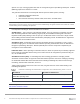
Make sure that the FC ports are up, for example: OS10# show interface status | grep 1/43 Fc 1/1/43:1 up 16G auto Fc 1/1/43:2 up 16G auto Fc 1/1/43:3 down 0 auto – Fc 1/1/43:4 down 0 auto – The show vfabric command output provides a variety of information including the default zone mode, the active zone set, and interfaces that are members of the vfabric.
06:c3:f9:a4:cd:03 0e:fc:00:01:01:00 f4:e9:d4:73:d0:0c 0e:fc:00:01:02:00 Eth 1/71/1 20:04:0f:00:ce:1d ~ 30 01:01:00 20:01:06:c3:f9:a4:cd:03 20:00:06:c3:f9:a4:cd:03 Eth 1/1/1 20:04:0f:00:ce:1d ~ 30 01:02:00 20:01:f4:e9:d4:73:d0:0c 20:00:f4:e9:d4:73:d0:00 Note: For more information on FC and FCoE, see the Dell EMC SmartFabric OS10 User Guide. 9.7 SmartFabric Services – Troubleshooting commands The following commands allow user to view various SmartFabric Services configuration information.
BZTQPK2 MX5108n 6L59XM2 MX5108n F13RPK2 MX5108n 9.7.4 fde1:53ba:e9a0:de14:2204:fff:fe00:19e5 SKY002Z B1 fde1:53ba:e9a0:de14:2204:fff:fe00:3de5 SKY002Z B2 fde1:53ba:e9a0:de14:2204:fff:fe00:a267 SKY003Z A2 ONLINE BACKUP ONLINE BACKUP ONLINE BACKUP show smartfabric details show smartfabric details command is used to see the all configured fabric details. This displays which nodes are part of the fabric, status of the fabric, and design type associated with the fabric.
Untagged-network : Networks : e6189b88-7f19-4b05-98b5-0c05ff7ff8c8, 284dae93-b91f4593-9cff-c8521cd7ae90 Configured-Interfaces : CBJXLN2:ethernet1/1/42:1, F13RPK2:ethernet1/1/41:1, F13RPK2:ethernet1/1/42:1, CBJXLN2:ethernet1/1/41:1 ------------------------------------------------------------------------------------------------------------------Name : FCoE Path B Description : ID : 0f7ad3a2-e59e-4a07-9a74-4e57558f0a4d Media Type : FC Native Vlan : 0 Untagged-network : Networks : e2c35ec5-c177-46f1-9a69-75d8b2
CBJXLN2 6L59XM2 D10DXC2 BZTQPK2 88 MX9116n MX5108n MX7116n MX5108n ONLINE ONLINE NOT-APPLICABLE ONLINE FABRIC SKY002Z FULL-SWITCH SKY002Z SKY003Z FULL-SWITCH SKY002Z Dell EMC PowerEdge MX SmartFabric Configuration and Troubleshooting Guide A1 B2 A1 B1
10 Uplink configuration scenarios 10.1 Scenario 1 - SmartFabric deployment with Dell EMC PowerSwitch Z9100-ON upstream switches Figure 80 shows the production topology using a pair of Dell EMC PowerSwitch Z9100-ONs as upstream switches. This section walks through configuring the Z9100-ON as well as validating the Z9100-ON configuration.
10.1.1 Dell EMC PowerSwitch Z9100-ON switch configuration The following section outlines the configuration commands issued to the Dell EMC PowerSwitch Z9100-ON switches. The switches start at their factory default settings per Appendix C.3. Note: The MX IOMs run Rapid Per-VLAN Spanning Tree Plus (RPVST+) by default. RPVST+ runs RSTP on each VLAN while RSTP runs a single instance of spanning tree across the default VLAN.
Configure the required VLANs on each switch. In this deployment example, the VLAN used is VLAN 10. Z9100-ON Leaf 1 Z9100-ON Leaf 2 interface vlan10 description “Company A General Purpose” no shutdown interface vlan10 description “Company A General Purpose” no shutdown Configure the port channels that connect to the downstream switches. The LACP protocol is used to create the dynamic LAG. Trunk ports allow tagged VLANs to traverse the trunk link. In this example, the trunk is configured allow VLAN 10.
10.1.2 Dell EMC PowerSwitch Z9100-ON validation This section contains validation commands for the Dell EMC PowerSwitch Z9100-ON leaf switches. 10.1.2.1 show vlt The show vlt command validates the VLT configuration status when the VLTi Link Status is up. The role of one switch in the VLT pair is primary, and its peer switch (not shown) is assigned the secondary role.
Configured hello time 2, max age 20, forward delay 15 Flush Interval 200 centi-sec, Flush Invocations 432 Flush Indication threshold 0 (MAC flush optimization is disabled) Interface Designated Name PortID Prio Cost Sts Cost Bridge ID PortID -------------------------------------------------------------------------------port-channel1 128.2517 128 50 FWD 0 32768 2004.
10.2 Scenario 2 - SmartFabric connected to Cisco Nexus 3232C switches Figure 81 shows the production topology using a pair of Cisco Nexus 3232C as leaf switches. This section configures the Cisco Nexus 3232Cs and creating a SmartFabric with the corresponding uplinks.
10.2.1 Cisco Nexus 3232C switch configuration The following section outlines the configuration commands issued to the Cisco Nexus 3232C leaf switches. Note: While this configuration example is specific to the Cisco Nexus 3232C switch, the same concepts apply to other Cisco Nexus and IOS switches. The switches start at their factory default settings, as described in Appendix C.4. Note: The MX IOMs run Rapid per-VLAN Spanning Tree Plus (RPVST+) by default.
Cisco Nexus 3232C Leaf 1 Cisco Nexus 3232C Leaf 2 vpc domain 255 peer-keepalive destination 100.67.162.200 vpc domain 255 peer-keepalive destination 100.67.162.
Note: If the connections to the MX switches do not come up, see Section 9 for troubleshooting steps. Trunk ports on switches allow tagged traffic to traverse the links. All flooded traffic for the a VLAN will be sent across trunk ports to all the switches even if those switches do not have associated VLAN. This takes up the network bandwidth with unnecessary traffic. VLAN or VTP Pruning is the feature that can be used to eliminate this unnecessary traffic by pruning the VLANs.
vPC status ---------------------------------------------------------------------id Port Status Consistency Reason Active vlans ---------- ----------- ----------------255 Po1 up success success 1,10 10.2.2.2 show vpc consistency-parameters The show vpc consistency-parameters command displays the configured values on all interfaces in the vPC. The displayed configurations are only those configurations that limit the vPC peer link and vPC from coming up.
10.2.2.3 show lldp neighbors The show lldp neighbors command provides information about lldp neighbors. In this example, Eth1/1 and Eth1/3 are connected to the two MX9116n FSEs, C160A2 and C140A1. The remaining links, Eth1/29 and Eth1/31, represent the vPC connection.
10.3 Scenario 3: Connect MX9116n FSE to Fibre Channel storage NPIV Proxy Gateway mode This chapter discusses a method for connecting the MX9116n FSE to a FC storage array connected to existing FC switches using the NPIV Proxy Gateway (NPG) mode for the connection. NPG mode allows for larger SAN deployments that aggregate I/O traffic at the NPG switch.
10.3.1 Configuration validation 10.3.1.1 show fc ns switch The show fc ns switch command shows all device ports logged into the fabric. In this deployment, four ports are logged in to each switch: two storage ports and two CNA ports.
10.3.1.2 show fcoe sessions The show fcoe sessions command shows active FCoE sessions. The output includes MAC addresses, Ethernet interfaces, the FCoE VLAN ID, FC IDs, and WWPNs of logged-in CNAs. Note: Due to the width of the command output, each line of output is shown on two lines below.
C140A1# show fc switch Switch Mode : FPORT Switch WWN : 10:00:e4:f0:04:6b:04:42 103 Dell EMC PowerEdge MX SmartFabric Configuration and Troubleshooting Guide
10.4 Scenario 4: Connect MX9116n FSE to Fibre Channel storage - FC Direct Attach This chapter discusses a method for connecting a FC storage array directly to the MX9116n FSE. As you can see, the steps to configure NPG mode or FC Direct Attach mode on the MX9116n FSE is different only by selecting which type of uplink is desired.
10.4.1 Configuration validation 10.4.1.1 show fc ns switch The show fc ns switch command shows all device ports logged into the fabric. In this deployment, four ports are logged in to each switch: two storage ports and two CNA ports.
10.4.1.2 show fcoe sessions The show fcoe sessions command shows active FCoE sessions. The output includes MAC addresses, Ethernet interfaces, the FCoE VLAN ID, FC IDs, and WWPNs of logged-in CNAs. Note: Due to the width of the command output, each line of output is shown on two lines below.
C140A1# show fc switch Switch Mode : FPORT Switch WWN : 10:00:e4:f0:04:6b:04:42 10.5 Scenario 5: Connect MX5108n to Fibre Channel storage - FSB This chapter provides instructions for connecting either the MX5108n or MX9116n to a Fibre Channel SAN via native FCoE uplinks. This connection type would be used in an environment where an existing switch such as the Dell EMC PowerSwitch S4148U has the capability to accept native FCoE and connect to native FC.
ToR switch 1 VLT S4148U-ON S4148U-ON (F_port mode) (F_port mode) ToR switch 2 FCoE SAN A FC SAN A FCoE SAN B FC SAN B Controller A MX5108n FSB mode (Leaf 1) VLT MX5108n FSB mode (Leaf 2) Controller B Unity500F 500F UnityUnity 500F MX7000 chassis FCoE (FSB) Network to Dell EMC Unity through F_port mode switch Note: See the Dell EMC SmartFabric OS10 Documentation for configuring NPG mode globally on the S4148UON switches. 10.5.
10.6 Scenario 6: Configure Boot from SAN The host OS of MX Server can boot from a remote FC storage array utilizing the IOMs. Booting to an OS through FC direct attach (F_port), FC (NPG), and FCoE (FSB) scenarios are supported.
4. 5. 6. 7. On the System Setup Main Menu, select Device Settings. Select the first CNA port. Select Device Level Configuration. Set Virtualization Mode to NPAR (if not already set), and click Back. Virtualization Mode to NPAR 8. Choose NIC Partitioning Configuration. 9. Select Partition 1 Configuration. 10. Set NIC + RDMA Mode to Disabled. Set the value of NIC + RDMA mode 11. Click Back to return. 12. Select Partition 2 Configuration. 13. Set FCoE Mode to Enabled as shown.
14. Click Back and select Back to go to Main Configuration Page. 15. Select NIC Configuration, then set the Boot Protocol to UEFI FCoE, and then click Back. Set the value of Boot Protocol to UEFI FCoE 16. If present, select Partition 3 Configuration in NIC Partitioning Configuration. Set all modes to Disabled and then click Back. 17. If present, select Partition 4 Configuration in NIC Partitioning Configuration. Set all modes to Disabled and then click Back. 18. Select FCoE Configuration. 19.
2. 3. 4. 5. Select Network Settings. Click Disable for all PXE Devices. Click Back. Click Finish, click Finish again, then select Yes to exit and reboot. Note: As previously documented, this server configuration may be used to generate a template to deploy to other servers with identical hardware. When a template is not used, repeat the steps in this chapter for each MX server sled that requires access to the FC storage. 10.6.
7. Click Finish when prompted on the Reboot System screen. 8. System reboots to Virtual Media. Press any key to boot install media when prompted. 9. Follow the OS prompts to install the OS to the FCoE storage LUN.
A Hardware used in this document This section covers the rack-mounted networking switches used in the examples in this guide. For detailed information on Hardware components related to MX Platform please see the Dell EMC PowerEdge MX Networking Architecture Guide. A.1 Dell EMC PowerSwitch S3048-ON The Dell EMC PowerSwitch S3048-ON is a 1-Rack Unit (RU) switch with forty-eight 1GbE BASE-T ports and four 10GbE SFP+ ports.
Provides up to 64 ports of 100GbE QSFP28 or up to 128 ports of 1/10/25/40/50GbE ports using breakout cables. This switch may be used as a leaf or spine switch in a Leaf-spine topology. Dell EMC PowerSwitch Z9264F-ON A.5 Dell EMC Unity 500F storage array The Unity 500F storage platform delivers all-flash storage with up to 8PB raw capacity. It has concurrent support for NAS, iSCSI, and FC protocols.
B Dell EMC Unity information This section shows how an administrator can determine the WWPNs of CNAs and storage targets. The WWPNs are used to connect FC storage targets to specific servers for file storage or OS boot. B.1 Determine Unity 500F storage array FC WWPNs The WWPNs of FC adapters in storage arrays are also used for FC configuration. WWPNs on Unity storage arrays are determined as follows: 1. Connect to the Unisphere GUI in a web browser and log in. 2.
B.2 CNA FCoE port WWPNs In this example the MX740c server's FCoE adapter World Wide Port Names (WWPNs) are used for FC connection configuration. Adapter WWPNs are determined as follows: 1. Connect to the first server's iDRAC in a web browser and log in. 2. Select System, then click Network Devices. 3. Click the CNA. In this example, it is NIC Mezzanine 1A. Under Ports and Partitioned Ports, the FCoE partition for each port is displayed as shown in Figure 102: FCoE partitions in iDRAC 4.
6. Repeat steps 4 and 5 for the FCoE partition on port 2. 7. Repeat in this section for the remaining MX740c servers. The FCoE WWPNs and MAC addresses used in this deployment example are shown in Table 10. Server CNA FCoE port WWPNs and MACs B.
Storage pool created B.3.2 Add hosts 1. 2. 3. 4. 5. 6. In the Unisphere left pane under ACCESS, select Hosts. On the Hosts tab, click the (+) icon, then click Host. Enter the Name of the server in the field provided, then click Next. Select the Initiator IQN/WWN checkbox in the Discovered Initiators panel. Click Next. Click Finish in the Review the host configuration page. Note: Additional hosts may be added as needed by clicking the B.3.3 Create LUNs and configure host access 1. 2. 3. 4. 5. 6. 7. 8.
10. On the Summary page, review the details and click Finish to create the LUN. 11. On the Results page, click Close when Overall status shows 100% Completed. The newly created LUN is now visible on the LUNs tab as shown in Figure 105. In this example, a LUN named FC-80GB that is 80GB in size has been created. LUN Created Create additional LUNs and grant access (map) to hosts as needed. Note: To modify host access at any time, check the box next to the LUN to select it.
C Additional information C.1 Delete MCM group To remove an MCM group using the OME-M console, perform the following steps: 1. Open the OME-M console. 2. In the MCM group pane, click the name of the lead chassis. 3. From the Configure menu, select Delete Group. 4. In the Delete Group dialog box, click Confirm. At this point, the OME-M console removes the MCM group. To manage the chassis, use the individual IP addresses assigned to each. C.
C.5 Connect to IO Module console port via RACADM To connect to an IOM console port, first connect to the OME-Modular IP address using SSH using the same credentials used to login to the OME-M GUI. Use the RACADM command from the MX9002m management module: racadm connect [-b] -m -b is for Binary mode -m is the Module option.
D Validated components D.1 Scenarios 1 and 2 The following tables include the hardware, software, and firmware used to configure and validate Scenario 1 and Scenario 2 in this document. D.1.1 Dell EMC PowerSwitches Dell EMC PowerSwitch switches and OS versions – Scenarios 1 and 2 D.1.2 Qty Item Version 2 Dell EMC PowerSwitch Z9100-ON leaf switches 10.4.0E(R3) 1 Dell EMC PowerSwitch S3048-ON OOB management switch 10.4.
D.1.3 Cisco Nexus switches Nexus switches and OS versions – Scenarios 1 and 2 D.2 Qty Item Version 2 Cisco Nexus 3232C 7.0(3)I4(1) Scenarios 3 and 4 The tables in this section include the hardware, software, and firmware used to configure and validate the examples in this document. Switches and OS versions Qty Item Software Version 1 Dell EMC PowerSwitch S3048-ON management switch 10.4.0E(R3P2) 2 Dell EMC Networking MX9116n FSE 10.5.0.1 2 Dell EMC Networking MX5108 10.5.0.
E Technical resources Dell EMC Networking Guides Dell EMC PowerEdge MX IO Guide Dell EMC PowerEdge MX Network Architecture Guide Dell EMC PowerEdge MX SmartFabric Deployment Video Dell EMC PowerEdge MX SmartFabric Deployment with Cisco ACI Video MX Port-Group Configuration Errors Video MX Port-Group Configuration Video Dell EMC OpenManage Enterprise-Modular Edition User's Guide v1.00.01 OS10 Enterprise Edition User Guide for PowerEdge MX IO Modules Release 10.4.
F Support and feedback Contacting Technical Support Support Contact Information Web: http://www.dell.com/support Telephone: USA: 1-800-945-3355 Feedback for this document Dell EMC encourages readers to provide feedback on the quality and usefulness of this publication by sending an email to Dell_Networking_Solutions@Dell.