
Install Guide

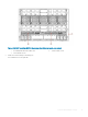
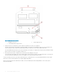
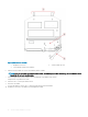
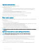

Figure 6. Release lever and latch
1
Backplane connectors 2 Switch module top view
3 Switch module release lever and latch
6 Slide the switch module out of the I/O module bay and set it aside.
NOTE
: If you do not insert a replacement switch module, to maintain proper airow and cooling, use a ller blade to ll the
empty slot. Do not leave the slot empty.
7 Insert the replacement switch module in the I/O module bay of the blade server chassis.
Complete this step within 60 seconds.
8 Insert the SFP+ or QSFP optical transceivers.
9 Reconnect the cables.
For more information, see the SFP+ or QSFP optical transceivers documentation.
10 Establish a connection to the blade server management module.
18
Switch module installation overview