
Install Guide
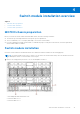
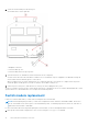
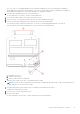
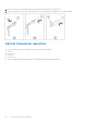
Table Of Contents
- MXG610s Fibre Channel Switch Module Installation Guide May 2021
- Contents
- About this guide
- Switch module overview
- Installation preparation
- Switch module installation overview
- Transceiver and cable installation
- Switch module monitoring
- Initial setup and verification
- Technical specifications
- Regulatory statements
- Caution and danger notices
- Dell EMC support

Optical transceivers
To avoid damage to the optical transceivers, handle them carefully.
Before installing an optical transceiver:
● The housing on the optical transceiver includes an integral guide key that prevents you from inserting the transceiver
incorrectly.
● Use minimal pressure when you insert an optical transceiver in the port. Forcing the transceiver into the port can damage
the transceiver or the switch module port.
● You can insert or remove an optical transceiver while the blade server chassis is powered on.
●
First insert the optical transceiver in the port before connecting the cables.
● Remove the cable from the optical transceiver before you remove the optical transceiver from the switch module.
To order Brocade-branded optical transceivers and cables, contact your sales representative.
For a complete list of optical transceivers and other interoperable hardware, see the Brocade website.
Fiber optic cables
After modifying the switch module IP address and domain name, cable all the external ports to the fabric connections before
bringing the switch module online.
To avoid damage to the fiber-optic cables:
● Do not route the cable along a folding cable-management arm.
● When you attach the cable to a device on the slide rails, leave enough slack in the cable. The cable cannot bend to a radius
of less than 5.08 cm (2 in.) when the device is extended or becomes pinched when the device retracts.
● Route the cable away from places where it may get snagged by other devices in the rack.
● Do not overtighten the cable straps, or bend the cables to a radius of less than 5.08 cm (2 in.).
● Dell EMC does not recommend tie wraps (also known as zip ties) for optical cables because you can easily overtighten them.
● Do not put excess weight on the cable at the connection point. Ensure that the cable is well supported.
NOTE:
Do not bend a cable to a radius of less than 5.08 cm (2 inches) under full tensile load and 3.048 cm (1.2 inches) with
no tensile load.
Optical transceivers and cabling installation
NOTE: When cabling SFP+ optical transceivers, start with port 0, then port 17, and then the other ports.
To insert the optical transceivers and the cable connections:
1. Insert the optical transceiver in an external port on the switch module until it is firmly seated and the latching mechanism
clicks.
Transceivers are keyed to ensure correct orientation. If a transceiver does not install easily, ensure that it is correctly
oriented.
2. Insert the fiber optic cable in the SFP+ or QSFP optical transceiver until the latching mechanism clicks.
Cable connectors are keyed to ensure correct orientation. If a cable connector does not install easily, ensure that it is
correctly oriented.
For instructions specific to a cable type, see the cable manufacturer’s documentation.
Optical transceiver removal and replacement
1. Disconnect the cable from the SFP+/QSFP optical transceiver.
NOTE:
Your SFP+/QSFP optical transceivers may differ slightly from the optical transceiver shown in the following
illustration, but the steps for removal are the same:
Transceiver and cable installation 17