
Install Guide
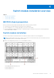
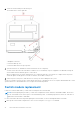
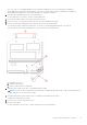
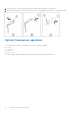
Table Of Contents
- MXG610s Fibre Channel Switch Module Installation Guide May 2021
- Contents
- About this guide
- Switch module overview
- Installation preparation
- Switch module installation overview
- Transceiver and cable installation
- Switch module monitoring
- Initial setup and verification
- Technical specifications
- Regulatory statements
- Caution and danger notices
- Dell EMC support

● The chassis comes with an electrostatic discharge (ESD) connector. To use the ESD connector, see the documentation
included with the chassis.
Electrical considerations
The MXG610s requires a maximum of 140 watts; the MX7000 chassis supplies 12 V power. Out of this 12 V power input, the
standby power supply supplies 3.3 V. No other power requirement or provision exists.
CAUTION: Do not attempt to replace the real-time clock (RTC) battery. There is danger of explosion if the
battery is incorrectly replaced or disposed off. If the real-time clock begins to lose time, contact your switch
module supplier.
Environmental considerations
Ensure proper cooling and ventilation. Verify the following:
● Air vents on the MX7000 are not blocked or restricted.
● Ambient air temperature at the front of the MX7000 does not exceed 40ºC (104ºF) while the switch module is operating.
Unpack
If you purchased the switch separately from the MX7000 chassis, the shipping carton includes one switch module with two,
four, or eight SWL 32-Gbps SFP+ transceivers pre-installed.
1. Open the shipping box and inspect the contents for damage.
NOTE:
Do not insert a damaged switch module in the blade server chassis. If the switch module is damaged, contact
your sales representative before proceeding.
2. Remove the foam layer that sits on top of the switch module.
3. Remove the switch module from the protective foam surround.
4. Remove the foam ends from the switch module.
5. Remove the orange protective cover from the internal connectors.
6. Slide the switch module out of the antistatic sleeve.
NOTE: Always follow standard ESD precautions.
Switch module information
Before installing the switch module, obtain the switch module serial number. To locate the serial number:
● Locate the serial number on the label attached to the top of the switch module. This label is not visible when you install the
switch module in the chassis.
● If you have installed the switch module, enter the chassisShow command. The switch module serial number displays along
with other data.
12
Installation preparation