
Users Guide

DRAC 5 Overview 23
Connectors
NOTE: The DRAC 5 hardware installation instructions can be found in the
Installing
a Remote Access Card
document or the
Installation and Troubleshooting Guide
included with your system.
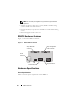
The DRAC 5 includes one onboard 10/100 Mbps RJ-45 NIC, a 50-pin
management cable, and a 44-pin MII cable. See Figure 1-1 for the DRAC 5
cable connectors.
The 50-pin management cable is the main interface to the DRAC that
provides connectivity to USB, serial, video, and an inter-integrated circuit
(I2C) bus. The 44-pin MII cable connects the DRAC NIC to the system’s
motherboard. The RJ-45 connector connects the DRAC NIC to an out-of-
band connection when the DRAC 5 is configured in Dedicated NIC mode.
Using the management and MII cables, you can configure your DRAC in
three separate modes, depending on your needs. See "DRAC Modes" on
page 225 in "Using the RACADM Command Line Interface" on page 209 for
more information.
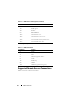
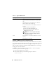
DRAC 5 Ports
Table 1-2 identifies the ports used by the DRAC 5 that listen for a server
connection. Table 1-3 identifies the ports that the DRAC 5 uses as a client.
This information is required when opening firewalls for remote access to a
DRAC 5.
Table 1-1. DRAC 5 Power Specifications
System Power
1.2 A on +3.3 V AUX (maximum)
550 mA on +3.3 V main (maximum)
0 mA on +5V main (maximum)
Table 1-2. DRAC 5 Server Listening Ports
Port Number Function
22*
Secure Shell (SSH)
23*
Telnet