
Reference Guide
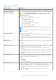
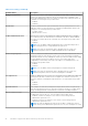
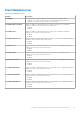
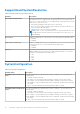
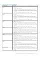
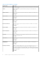
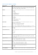
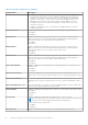
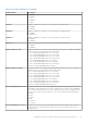
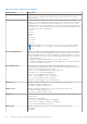
Table Of Contents
- Dell Command | PowerShell Provider Version 2.4 Reference Guide
- Introduction to Dell Command | PowerShell Provider 2.4
- Attributes supported in Dell Command | PowerShell Provider 2.4
- AdvancedBootOptions
- AdvancedConfigurations
- BatteryInformation
- BIOSSetupAdvancedMode
- BootSequence
- Connection
- Integrated Devices
- IntelSoftwareGuardExtensions
- Keyboard
- Manageability
- Maintenance
- MemoryInformation
- MiscellaneousDevices
- Passwords
- Performance
- POSTBehavior
- PowerManagement
- PreEnabled
- ProcessorInformation
- SecureBoot
- Security
- StealthModeControl
- SupportAssistSystemResolution
- SystemConfiguration
- SystemInformation
- SystemLogs
- ThermalConfiguration
- TPMSecurity
- USBConfiguration
- Video
- VirtualizationSupport
- Wireless
- Error reporting in Dell Command | PowerShell Provider 2.4
- Accessing documents from the Dell EMC support site

Table 25. SystemConfiguration (continued)
Attribute Name Description
AnalogDigitalInterfaceModeCha
nnel3
Sets the defined Analog or Digital Interface mode for channel 3. The following are the
possible values:
● Unused—Channel is unused.
● ADCInput—Sets the channel mode as Analog-to-Digital Converter (ADC) input.
● DACOutput—Sets the channel mode as Digital-to-Analog Converter (DAC) output.
● DACAndADC—Sets the channel mode as DAC output, but can be monitored through
ADC input.
● GPIO—Sets the channel mode as General Purpose Input or Output.
AnalogDigitalInterfaceModeCha
nnel4
Sets the defined Analog or Digital Interface mode for channel 4. The following are the
possible values:
● Unused—Channel is unused.
● ADCInput—Sets the channel mode as Analog-to-Digital Converter (ADC) input.
● DACOutput—Sets the channel mode as Digital-to-Analog Converter (DAC) output.
● DACAndADC—Sets the channel mode as DAC output, but can be monitored through
ADC input.
● GPIO—Sets the channel mode as General Purpose Input or Output.
AnalogDigitalInterfaceModeCha
nnel5
Sets the defined Analog or Digital Interface mode for channel 5. The following are the
possible values:
● Unused—Channel is unused.
● ADCInput—Sets the channel mode as Analog-to-Digital Converter (ADC) input.
● DACOutput—Sets the channel mode as Digital-to-Analog Converter (DAC) output.
● DACAndADC—Sets the channel mode as DAC output, but can be monitored through
ADC input.
● GPIO—Sets the channel mode as General Purpose Input or Output.
AnalogDigitalInterfaceModeCha
nnel6
Sets the defined Analog or Digital Interface mode for channel 6. The following are the
possible values:
● Unused—Channel is unused.
● ADCInput—Sets the channel mode as Analog-to-Digital Converter (ADC) input.
● DACOutput—Sets the channel mode as Digital-to-Analog Converter (DAC) output.
● DACAndADC—Sets the channel mode as DAC output, but can be monitored through
ADC input.
● GPIO—Sets the channel mode as General Purpose Input or Output.
AnalogDigitalInterfaceModeCha
nnel7
Sets the defined Analog or Digital Interface mode for channel 7. The following are the
possible values:
● Unused—Channel is unused.
● ADCInput—Sets the channel mode as Analog-to-Digital Converter (ADC) input.
● DACOutput—Sets the channel mode as Digital-to-Analog Converter (DAC) output.
● DACAndADC—Sets the channel mode as DAC output, but can be monitored through
ADC input.
● GPIO—Sets the channel mode as General Purpose Input or Output.
AnalogDigitalInterfaceModeCha
nnel8
Sets the defined Analog or Digital Interface mode for channel 8. The following are the
possible values:
● Unused—Channel is unused.
● ADCInput—Sets the channel mode as Analog-to-Digital Converter (ADC) input.
● DACOutput—Sets the channel mode as Digital-to-Analog Converter (DAC) output.
● DACAndADC—Sets the channel mode as DAC output, but can be monitored through
ADC input.
● GPIO—Sets the channel mode as General Purpose Input or Output.
BatteryFuelGauge This feature controls the battery fuel gauge. The following are the possible values:
● Enabled—Enabling this feature allows the battery fuel gauge to be activated on touch
or swipe.
Attributes supported in Dell Command | PowerShell Provider 2.4 35