Dell Command | PowerShell Provider Version 1.
Notes, cautions, and warnings NOTE: A NOTE indicates important information that helps you make better use of your computer. CAUTION: A CAUTION indicates either potential damage to hardware or loss of data and tells you how to avoid the problem. WARNING: A WARNING indicates a potential for property damage, personal injury, or death. Copyright © 2015 - 2016 Dell Inc. All rights reserved. This product is protected by U.S. and international copyright and intellectual property laws.
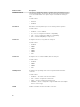
Contents 1 Introduction........................................................................................................... 4 Other documents you may need......................................................................................................... 4 2 Attributes supported in Dell Command | PowerShell Provider................... 5 SystemInformation................................................................................................................................
Introduction 1 Dell Command | PowerShell Provider is a PowerShell module that provides BIOS configuration capability to Dell client platforms using the Windows PowerShell Interface. Dell Command | PowerShell Provider can be installed as plug-in software registered within a Windows PowerShell environment. This document describes the supported attributes, and error reporting in Dell Command | PowerShell Provider.
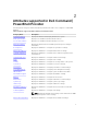
Attributes supported in Dell Command | PowerShell Provider 2 Following are the categories in Dell Command | PowerShell Provider. These categories contain BIOS attributes. Table 1. Attributes supported in Dell Command | PowerShell Provider Category Name Description SystemInformation Displays information that uniquely identifies the system. MemoryInformation Displays non-editable information about memory. ProcesserInformation Displays non-editable information about processor(s).
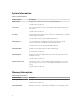
SystemInformation Table 2. SystemInformation Attribute Name Description BIOS Version Displays the current version of the system BIOS firmware. Possible values: Read-only ServiceTag The service tag is the system’s serial number that uniquely identifies the Dell system. Possible values: Read-only AssetTag An asset tag is a string that can be used by an IT administrator to uniquely identify a particular system.
Attribute Name Description NOTE: Due to an amount of memory allocated for the system use, MemoryAvailable is less than MemoryInstalled. Certain operating systems may not be able to use all the available memory. Possible Values: Read-only MemorySpeed Displays the clock frequency of the main memory. Possible Values: Read-only MemoryTechnology Displays the technology of the main memory installed in the system.
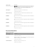
Attribute Name Description MaximumClockSpeed Displays the maximum speed supported by the processor. Possible values: Read-only ProcessorL2Cache Displays the L2 cache size. Possible values: Read-only ProcessorL3Cache Displays the L3 cache size. Possible values: Read-only HTCapable Specifies whether the system supports Hyper Threading (HT). Possible values: Read-only 64-BitTechnology Specifies whether the installed processor(s) support 64-bit extensions.
AdvanceBootOptions Table 7. AdvanceBootOptions Attribute Name Description EnableLegacyOptionROMs If enabled, allows legacy option ROMs to load. Without this option, only UEFI option ROMs loads. This option is required for Legacy boot mode. This mode cannot be enabled with Secure Boot. Possible values: • • Enabled Disabled SystemConfiguration Table 8. SystemConfiguration Attribute Name Description IntegratedNIC Controls the state of on-board LAN controller 1.
Attribute Name Description UEFINetworkStack This option is disabled by default. If enabled, UEFI networking protocols are installed/available, allowing pre-OS and early OS networking features to use the enabled NICs. This option may be used without turning on PXE. Possible values: • • ParallelPort Enabled Disabled Determines how the parallel port on the docking station operates. Possible values: • • • • SerialPort1 Disabled — Port is disabled. AT — Port is configured for IBM AT compatibility.
Attribute Name Description Possible values: • • SATA1 Enabled Disabled Enables or disables the second SATA drive controller. Possible values: • • SATA2 Enabled Disabled Enables or disables the third SATA drive controller. Possible values: • • SATA3 Enabled Disabled Enables or disables the fourth SATA drive controller. Possible values: • • SATA4 Enabled Disabled Enables or disables the fifth SATA drive controller.
Attribute Name Description SMARTReporting Controls whether hard drive errors for integrated drives are reported during system startup. Possible values: • • PCIBus Enabled Disabled Sets the maximum number of PCI busses to 64,128 or 256. Possible values: • • OSDButton Enables or disables the On-screen Display (OSD) buttons on an All-InOne system. When disabled, pressing these buttons has no effect.
Attribute Name Description Possible values: • • Audio Enabled — Charges the external devices, such as phones and laptop music players, using the stored system battery when the system is turned off or in sleep mode. This feature works only if: – The device is connected through the USB PowerShare port on the laptop. – The system is connected to an AC power source. – The battery charge is less than 50 percent.
Attribute Name Description NOTE: If value NoColor is selected, you cannot use to switch to another keyboard backlight color. The value NoColor cannot be combined with any other color. KeyboardBacklightActiveCo Displays or sets an active color for the keyboard backlight in a rugged system. Six colors are available: four predefined colors (white, red, green, lor blue), and two user configurable colors (custom1 and custom2). Active color indicates the color used on startup.
StealthModeControl Table 9. StealthModeControl Attribute Description StealthMode Sets the behavior of system elements. Possible values: • • StealthModeLEDs Enabled — The system elements operate in the preprogrammed stealth mode. Disabled — The system elements operate in normal mode. Enables or disables Stealth Mode behavior for LEDs if the StealthMode attribute is enabled.
Attribute Description StealthModeGPSReceiver Enables or disables Stealth Mode behavior for GPS receiver if the StealthMode attribute is enabled. Possible values: • • StealthModeWLANRadio Enabled Disabled Enables or disables Stealth Mode behavior for WLAN radio if the StealthMode attribute is enabled. Possible values: • • StealthModeWWANRadio Enabled Disabled Enables or disables Stealth Mode behavior for WWAN radio if the StealthMode attribute is enabled.
Attribute Name Description SwitchableGraphics Enables or disables switchable graphics technologies such as NVIDIA, Optimus, and AMD PowerExpress. Possible values: • • PrimaryDisplay Enabled Disabled Selects which PCI Express slot contains the primary boot video device. A monitor connected to the primary video device displays BIOS setup and initial operating system text and graphics. Possible values: • • • 0 — Sets the onboard video device slot as the primary video device slot.
Attribute Name Description AdminPassword Sets, changes, or clears the administrator (admin) password (also called the setup password). If you delete the admin password, the system password, if set, is also deleted. Possible values: String containing minimum 4 and maximum 32 characters including whitespace. SystemPassword Sets, changes, or clears the system password (also known as the user password). Enter the system password, if set, when the system is powered on.
Attribute Name Description SecureBootPolicy Configures the secure boot policy. • • ChassisIntrusion Standard — The BIOS uses the system manufacturer's keys and certificates to authenticate preboot images. Custom — The BIOS uses user-defined keys and certificates. Secure Boot Policy is Standard by default. The chassis intrusion switch is a physical switch which triggers an event when the chassis is opened.
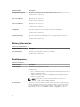
Performance Table 13. Performance Attribute Name Description MultiCoreSupport Specifies whether the processor has one or more cores enabled. The performances of some applications improve with additional cores. Possible values: • • • • • • • • • • IntelSpeedStep All — All cores are enabled. 1 — Only one core is enabled. 2 — Two cores are enabled. 4— Four cores are enabled. 6— Six cores are enabled. 8— Eight cores are enabled. 10 — Ten cores are enabled. 12 — Twelve cores are enabled.
Attribute Name Description Possible values: • • HardwarePrefetcher Enabled Disabled Enables or disables the CPU's hardware prefetcher. If enabled, the processor's Hardware Prefetcher will automatically prefetch data and code for the processor. Possible values: • • AdjacentCacheLinePrefetc h Enabled Disabled Enables or disables AdjacentCacheLinePrefetch feature. Possible values: • • Enabled - CPU fetches the adjacent cache line in the other half of the sector.
Attribute Name Description LimitCPUIDValue Restricts the maximum CPUID functions supported by the processor. Some operating system does not complete the installation when more than three CPUID functions are supported. Possible values: • • Enabled Disabled PowerManagement Table 14. PowerManagement Attribute Name Description AutoOn Configures the days when the system has to turn on automatically at the time specified in AutoOnHour and AutoOnMinute.
Attribute Name Description Possible values: • • AutoOnTuesday Enabled Disabled Enables or disables the AutoOn functionality at the specified time on Tuesdays. Possible values: • • AutoOnWednesday Enabled Disabled Enables or disables the AutoOn functionality at the specified time on Wednesdays Possible values: • • AutoOnThursday Enabled Disabled Enables or disables the AutoOn functionality at the specified time on Thursdays.
Attribute Name Description PeakShiftBatteryThreshold Sets the value of the Peak Shift battery threshold. The acceptable value range is from 15 to 100 percent. When the Peak Shift battery threshold level is reached, the system starts using AC power. Possible values: Integers ranging from 15 to 100 PeakShiftDayConfiguratio n Configures the days settings based on StartTime, EndTime, and ChargeStartTime.
Attribute Name Description Possible values: • • • • • • USBWakeSupport Auto High Medium Low Medium High Medium Low Enables USB devices to wake the system from Standby. NOTE: This feature is functional only when the AC power adapter is connected. Possible values: • • FanControlOverride Enabled Disabled Runs the system fan at full speed. Possible values: • • ACRecovery Enabled Disabled Controls the system's behavior when AC power is restored after AC power has been lost.
Attribute Name Description WakeonLANorWLAN Enables the system to turn on from the off state when triggered by a special LAN signal, or from the hibernate state when triggered by a special wireless LAN signal. Possible values: • • • • • BlockSleepS3State Enabled — Allows the system to power on when it receives a wakeup signal from the LAN or wireless LAN. Disabled — Does not allow the system to power on when it receives a wakeup signal from the LAN or wireless LAN.
Attribute Name Description NOTE: Primary Battery Custom Charge Start percentage must be less than Primary Battery Custom Charge End percent and the minimum difference between the two must be 5 percent. Possible values: Integers ranging from 55 to 100 BatterySliceChargeConfig uration Configures the battery slice charge mode. The battery slice is an external battery that docks with the system docking connector. The battery slice houses its own battery charger.
Attribute Name Description Possible values: • • Keypad Enabled Disabled Activates the internal keyboard's embedded keypad either when Numlock LED is on or when the Fn key is pressed. NOTE: When Setup is running, this option has no effect, Setup works in the Fn Key Only mode. Possible values: • • MouseTouchpad Fn Key Only — The keypad is enabled only when you hold the Fn key. By Numlock — The keypad is enabled when, the Numlock LED is On and no external keyboard is attached.
Attribute Name Description • FnLock Disabled This option controls the behavior of the dual function keys, when Fn key is pressed and when it is not. Possible values: • • FnLockMode Enabled — Fn+Esc key combination toggles the primary behavior of F1 to F12 keys between their normal and secondary functions. Disabled — You cannot toggle the primary behavior of these keys. If Enabled, F1 to F12 keys behave as function keys holding Fn key is required to access their secondary functions.
VirtualizationSupport Table 16. VirtualizationSupport Attribute Description Virtualization Enables or disables the VT technology in applicable CPUs. Trusted execution required for Virtualization technology to be enabled. Possible values: • • VTforDirectIO Enabled Disabled Determines whether a Virtual Machine Monitor (VMM) can utilize the additional hardware capabilities provided by Intel Virtualization Technology for Direct IO.
Attribute Name Description Possible values: • • WirelessSwitchBluetoothC ontrol Determines that bluetooth is controlled by the wireless On-Off switch. Possible values: • • WirelessSwitchWWANWiGi gControl Enabled — Physical wireless On-Off switch can turn the WLAN OnOff. Disabled — Physical wireless On-Off switch will not be able to turn the WLAN On-Off. Enabled — Physical wireless On-Off switch can turn the bluetooth On-Off.
Attribute Name Description LidMountedWirelessActivit yLED This additional LED is mounted in the lid in a visible position. Possible values: • • Always Off — The LED always stays off irrespective of network activity. LED Indicates Wireless Activity Status — The LED becomes active whenever any of the wireless devices are capable of connecting to a wireless network. Wireless activity is defined as the following three inputs: – WWAN activity – Bluetooth activity – Wi-Fi activity Maintenance Table 18.
Attribute Name Description Possible values: • • Enabled — BIOS turns on the TPM during POST, and can be used by the operating system. Disabled — BIOS does not on the TPM during POST, and the TPM is nonfunctional and invisible to the operating system. NOTE: Disabling this option does not change any TPM settings that you may have configured nor does it delete or change any information or keys you may have stored there. It simply turns off the TPM so that it cannot be used.
Attribute Name Description Possible values: • • ModuleBay Enabled Disabled Enables or disables the module bay. The module bay is a hot-pluggable bay where storage and media devices such as HDDs, CDs or DVDs can be installed. Possible values: • • Microphone Enabled Disabled Enables or disables the internal or external microphone. Possible values: • • ExpressCard Enabled Disabled Enables or disables the ExpressCard.
Attribute Name Description • MediaCard Disabled Enables or disables the media card. If disabled, the media card is hidden from the OS and not seen in the Device Manager. Possible values: • • MediaCardand1394 Enabled Disabled Enables or disables the media card and 1394. Possible values: • • PCCard Enabled Disabled Enables or disables the PCMCIA device slot. Possible values: • • Enabled Disabled USBConfiguration Table 22.
Attribute Name Description • DockingStationDevicesexc eptvideoon Disabled Enables or disables all devices such as serial, audio, LAN, and USB ports in the docking station. Possible values: • • Enabled Disabled NOTE: This option works only when ExternalUSBPort is enabled. SideUSBPorts Enables or disables all side USB Ports in the system. Possible values: • • FrontUSBPorts Enabled Disabled Enables or disables all front USB Ports in the systems.
AdvancedConfigurations Table 23. AdvancedConfigurations Attribute Name Description ASPM Set the ASPM (Active State Power Management) level. Possible values: • • • Auto — There is handshaking between the device and PCI Express hub to determine the best ASPM mode supported by the device. Disabled — ASPM power management is turned off always. L1 Only — ASPM power management is set to use L1.
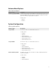
Error reporting in Dell Command | PowerShell Provider 3 Dell Command | PowerShell Provider provides an Error Reporting feature. Dell Command | PowerShell Provider uses the PowerShell ErrorVariable parameter to capture the ErrorRecord. This ErrorVariable can be used to get more information such as exception, error id, error category, and recommended action etc. about an error. Example: To set the error variable. gi .\POSTBehavior\numl -ErrorVariable ev Example: To see more information about the error. $ev.
Error Category Error ID Scenarios Example InvalidData InvalidPossibleVal ue Using set-item cmdlet for an si .\POSTBehavior\Numlock attribute with Invalid possible value. “on” NumberNotInRan ge Doing set operation by giving out of si .\AutoOnHour “54” range integer value for an attribute which accepts integer value in a si .\AutoOnMinute “67” particular range. si .\PeakShiftBatteryThreshold “13” NotValidNumber Doing set operation by giving noninteger value for an attribute accepts integer value.
Error Category Error ID Scenarios InvalidCombinatio Trying to set colors for nOfNoColorAndS KeyboardBacklightEnabledColors with NoColor Value upportedColors DuplicateColorNa me Trying to provide same color more than once for KeyboardBacklightEnabledColors OnlyOneColorAllo Trying to set multiple colors for wedForActiveColo KeyboardBacklightActiveColor r Example si . \KeyboardBacklightEnabledColr os “Red,White,Custom1,NoColor” si . \KeyboardBacklightEnabledColr os “Red,White,Custom1,Custom1” si . \Keybo
Accessing documents from Dell support site 4 You can access the required documents in one of the following ways: • Using the following links: – For all Enterprise Systems Management documents — Dell.com/SoftwareSecurityManuals – For OpenManage documents — Dell.com/OpenManageManuals – For Remote Enterprise Systems Management documents — Dell.com/esmmanuals – For OpenManage Connections Enterprise Systems Management documents — Dell.