
Reference Guide
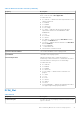
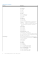
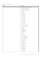

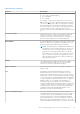

Table Of Contents
- Dell Command | Monitor Version 10.3 Reference Guide
- Introduction for Dell Command | Monitor 10.3
- Dell Command | Monitor 10.3 Namespaces
- Profiles for Dell Command | Monitor 10.3
- Classes for Dell Command | Monitor 10.3
- Dell Command | Monitor 10.3 classes and properties
- Classes supported for systems running Linux
- Classes supported for systems running Windows
- DCIM_AlertIndication
- DCIM_ApplicationProxySetting
- DCIM_BaseMetricDefinition
- DCIM_Card
- DCIM_Chassis
- DCIM_Chip
- DCIM_DesktopMonitor
- DCIM_DHCPProtocolEndpoint
- DCIM_EthernetPort
- DCIM_FlatPanel
- DCIM_IPProtocolEndpoint
- DCIM_ImprovementProgramConsent
- DCIM_ControllerView
- DCIM_PhysicalDiskView
- DCIM_VirtualDiskView
- DCIM_PhysicalMemory
- DCIM_PhysicalPackage
- DCIM_ParallelPort
- DCIM_RemoteServiceAccessPoint
- DCIM_Slot
- DCIM_SerialPort
- DCIM_USBPort
- DCIM_Memory
- DCIM_PCIDevice
- DCIM_DisplayController
- DCIM_Fan
- DCIM_IndicatorLED
- DCIM_PowerSupply
- DCIM_Battery
- DCIM_Processor
- DCIM_NumericSensor
- DCIM_Sensor
- DCIM_DeviceBay
- DCIM_VideoHead
- DCIM_Button
- DCIM_LCDPanel
- DCIM_NetworkPortConfigurationService
- DCIM_TimeService
- DCIM_AccountManagementService
- DCIM_RoleBasedAuthorizationService
- DCIM_PowerManagementService
- DCIM_BootService
- DCIM_IPConfigurationService
- DCIM_PowerUtilizationManagementService
- DCIM_BIOSService
- DCIM_SoftwareInstallationService
- DCIM_ComputerSystem
- DCIM_RecordLog
- DCIM_OperatingSystem
- DCIM_SoftwareIdentity
- DCIM_BIOSElement
- DCIM_ConcreteJob
- DCIM_BootSourceSetting
- DCIM_BootConfigSetting
- DCIM_IPAssignmentSettingData
- DCIM_PowerAllocationSettingData
- DCIM_AssetAcquisition
- DCIM_AssetExtendedWarrantyInformation
- DCIM_AssetOwnerInformation
- DCIM_AssetSupportInformation
- DCIM_AssetWarrantyInformation
- DCIM_AssetSystemInformation
- DCIM_ThermalInformation
- DCIM_AMTSettings
- DCIM_ASFSettings
- DCIM_VProSettings
- DCIM_AlertIndicationSettingData
- DCIM_HDDAlertIndicationSettingData
- DCIM_BaseMetricValue
- DCIM_LogEntry
- DCIM_IndicatorLEDCapabilities
- DCIM_ProcessorCapabilities
- DCIM_AccountManagementCapabilities
- DCIM_BootServiceCapabilities
- DCIM_PlatformWatchdogServiceCapabilities
- DCIM_DHCPCapabilities
- DCIM_PowerUtilizationManagementCapabilities
- DCIM_EnabledLogicalElementCapabilities
- DCIM_ButtonCapabilities
- DCIM_LCDPanelCapabilities
- DCIM_PowerManagementCapabilities
- DCIM_PhysicalAssetCapabilities
- DCIM_RoleBasedManagementCapabilities
- DCIM_AllocationCapabilities
- DCIM_BIOSServiceCapabilities
- DCIM_SoftwareInstallationServiceCapabilities
- DCIM_ConcreteCollection
- DCIM_RedundancySet
- DCIM_Role
- DCIM_IndicationSettingCollection
- DCIM_ConfigurationCapacity
- DCIM_Location
- DCIM_BIOSEnumeration
- DCIM_BIOSPassword
- DCIM_BIOSString
- DCIM_MemoryError
- DCIM_IdentityContext
- DCIM_OrderedComponent
- DCIM_Container
- DCIM_ConcreteComponent
- DCIM_SystemDevice
- DCIM_AccountOnSystem
- DCIM_InstalledOS
- DCIM_SystemBIOS
- DCIM_SystemComponent
- DCIM_SettingsDefineCapabilities
- DCIM_DeviceSAPImplementation
- DCIM_HostedAccessPoint
- DCIM_HostedCollection
- DCIM_HostedService
- DCIM_VideoHeadOnController
- DCIM_SAPSAPDependency
- DCIM_ReferencedProfile
- DCIM_MetricDefForME
- DCIM_MetricForME
- DCIM_MetricInstance
- DCIM_ElementInConnector
- DCIM_Docked
- DCIM_ConcreteDependency
- DCIM_Realizes
- DCIM_ComputerSystemPackage
- DCIM_RunningOS
- DCIM_UseOfLog
- DCIM_AssociatedIndicatorLED
- DCIM_AssociatedCacheMemory
- DCIM_AssociatedSensor
- DCIM_RemoteAccessAvailableToElement
- DCIM_ServiceServiceDependency
- DCIM_DeviceConnection
- DCIM_ElementSoftwareIdentity
- DCIM_ElementCapabilities
- DCIM_ElementSettingData
- DCIM_OrderedMemberOfCollection
- DCIM_MemberOfCollection
- DCIM_OwningCollectionElement
- DCIM_ElementConformsToProfile
- DCIM_RoleLimitedToTarget
- DCIM_ElementCapacity
- DCIM_ServiceAffectsElement
- DCIM_AssociatedPowerManagementService
- DCIM_ServiceAvailableToElement
- DCIM_LogManagesRecord
- DCIM_InstalledSoftwareIdentity
- DCIM_ConcreteIdentity
- DCIM_SMARTAttributeInfo
- DCIM_SettingsDefineState
- DCIM_ElementLocation
- DCIM_CredentialContext
- DCIM_OwningJobElement
- BIOS settings supported in Dell Command | Monitor 10.3
- Alerts in Dell Command | Monitor 10.3
- Sample scripts for Dell Command | Monitor 10.3

Table 20. Slot (continued)
Property Description
Possible values are:
● 0 = Unknown
● 1 = Other
● 2 = RS232
● 3 = BNC
● 4 = RJ11
● 5 = RJ45
● 6 = DB9
● 7 = Slot
● 8 = SCSI High Density
● 9 = SCSI Low Density
● 10 = Ribbon
● 11 = AUI
● 12 = Fiber SC
● 13 = Fiber ST
● 14 = FDDI-MIC
● 15 = Fiber-RTMJ
● 16 = PCI — Describes the generic PCI connector layout.
● 17 = PCI-X — Describes the PCI Extended connector
layout.
●
18 = PCI-E — Describes the PCI Express connector layout,
where the actual layout with respect to the length is
unknown.
● 19 = PCI-E x1
● 20 = PCI-E x2
● 21 = PCI-E x4
● 22 = PCI-E x8
● 23 = PCI-E x16
● 24 = PCI-E x32
● 25 = PCI-E x64
● 26..32567 = DMTF Reserved
● 32568..65535 = Vendor Reserved
19 — 25 (PCI-E xN) — Describes the PCI Express connector
layout, where N is the lane count that appropriately describes
the length of the PCI-E connector.
ConnectorType
An array of integers defining the type of PhysicalConnector.
An array is specified to allow the description of combinations
of Connector information.
Possible values are:
● 0 = Unknown
● 1 = Other
● 2 = Male
● 3 = Female
● 4 = Shielded
●
5 = Unshielded
● 6 = SCSI (A) High-Density (50 pins)
● 7 = SCSI (A) Low-Density (50 pins)
● 8 = SCSI (P) High-Density (68 pins)
● 9 = SCSI SCA-I (80 pins)
● 10 = SCSI SCA-II (80 pins)
● 11 = Fibre Channel (DB-9, Copper)
● 12 = Fibre Channel (Optical Fibre)
72 Dell Command | Monitor 10.3 classes and properties