
Reference Guide
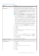


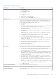
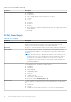
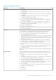

Table Of Contents
- Dell Command | Monitor Version 10.5 Reference Guide
- Contents
- Introduction for Dell Command | Monitor 10.5
- Dell Command | Monitor 10.5 Namespaces
- Profiles for Dell Command | Monitor 10.5
- Classes for Dell Command | Monitor 10.5
- Dell Command | Monitor 10.5 classes and properties
- Classes supported for systems running Linux
- Classes supported for systems running Windows
- DCIM_AlertIndication
- DCIM_ApplicationProxySetting
- DCIM_BaseMetricDefinition
- DCIM_Card
- DCIM_Chassis
- DCIM_Chip
- DCIM_DesktopMonitor
- DCIM_DHCPProtocolEndpoint
- DCIM_EthernetPort
- DCIM_FlatPanel
- DCIM_IPProtocolEndpoint
- DCIM_ImprovementProgramConsent
- DCIM_ControllerView
- DCIM_PhysicalDiskView
- DCIM_VirtualDiskView
- DCIM_PhysicalMemory
- DCIM_PhysicalPackage
- DCIM_ParallelPort
- DCIM_RemoteServiceAccessPoint
- DCIM_Slot
- DCIM_SerialPort
- DCIM_USBPort
- DCIM_Memory
- DCIM_PCIDevice
- DCIM_DisplayController
- DCIM_Fan
- DCIM_IndicatorLED
- DCIM_PowerSupply
- DCIM_Battery
- DCIM_Processor
- DCIM_NumericSensor
- DCIM_Sensor
- DCIM_DeviceBay
- DCIM_VideoHead
- DCIM_Button
- DCIM_LCDPanel
- DCIM_NetworkPortConfigurationService
- DCIM_TimeService
- DCIM_AccountManagementService
- DCIM_RoleBasedAuthorizationService
- DCIM_PowerManagementService
- DCIM_BootService
- DCIM_IPConfigurationService
- DCIM_PowerUtilizationManagementService
- DCIM_BIOSService
- DCIM_SoftwareInstallationService
- DCIM_ComputerSystem
- DCIM_RecordLog
- DCIM_OperatingSystem
- DCIM_SoftwareIdentity
- DCIM_BIOSElement
- DCIM_ConcreteJob
- DCIM_BootSourceSetting
- DCIM_BootConfigSetting
- DCIM_IPAssignmentSettingData
- DCIM_PowerAllocationSettingData
- DCIM_AssetAcquisition
- DCIM_AssetExtendedWarrantyInformation
- DCIM_AssetOwnerInformation
- DCIM_AssetSupportInformation
- DCIM_AssetWarrantyInformation
- DCIM_AssetSystemInformation
- DCIM_ThermalInformation
- DCIM_AMTSettings
- DCIM_ASFSettings
- DCIM_VProSettings
- DCIM_AlertIndicationSettingData
- DCIM_HDDAlertIndicationSettingData
- DCIM_BaseMetricValue
- DCIM_LogEntry
- DCIM_IndicatorLEDCapabilities
- DCIM_ProcessorCapabilities
- DCIM_AccountManagementCapabilities
- DCIM_BootServiceCapabilities
- DCIM_PlatformWatchdogServiceCapabilities
- DCIM_DHCPCapabilities
- DCIM_PowerUtilizationManagementCapabilities
- DCIM_EnabledLogicalElementCapabilities
- DCIM_ButtonCapabilities
- DCIM_LCDPanelCapabilities
- DCIM_PowerManagement
- DCIM_PhysicalAssetCapabilities
- DCIM_RoleBasedManagementCapabilities
- DCIM_AllocationCapabilities
- DCIM_BIOSServiceCapabilities
- DCIM_SoftwareInstallationServiceCapabilities
- DCIM_ConcreteCollection
- DCIM_RedundancySet
- DCIM_Role
- DCIM_IndicationSettingCollection
- DCIM_ConfigurationCapacity
- DCIM_Location
- DCIM_BIOSEnumeration
- DCIM_BIOSPassword
- DCIM_BIOSString
- DCIM_MemoryError
- DCIM_IdentityContext
- DCIM_OrderedComponent
- DCIM_Container
- DCIM_ConcreteComponent
- DCIM_SystemDevice
- DCIM_AccountOnSystem
- DCIM_InstalledOS
- DCIM_SystemBIOS
- DCIM_SystemComponent
- DCIM_SettingsDefineCapabilities
- DCIM_DeviceSAPImplementation
- DCIM_HostedAccessPoint
- DCIM_HostedCollection
- DCIM_HostedService
- DCIM_VideoHeadOnController
- DCIM_SAPSAPDependency
- DCIM_ReferencedProfile
- DCIM_MetricDefForME
- DCIM_MetricForME
- DCIM_MetricInstance
- DCIM_ElementInConnector
- DCIM_Docked
- DCIM_ConcreteDependency
- DCIM_Realizes
- DCIM_ComputerSystemPackage
- DCIM_RunningOS
- DCIM_UseOfLog
- DCIM_AssociatedIndicatorLED
- DCIM_AssociatedCacheMemory
- DCIM_AssociatedSensor
- DCIM_RemoteAccessAvailableToElement
- DCIM_ServiceServiceDependency
- DCIM_DeviceConnection
- DCIM_ElementSoftwareIdentity
- DCIM_ElementCapabilities
- DCIM_ElementSettingData
- DCIM_OrderedMemberOfCollection
- DCIM_MemberOfCollection
- DCIM_OwningCollectionElement
- DCIM_ElementConformsToProfile
- DCIM_RoleLimitedToTarget
- DCIM_ElementCapacity
- DCIM_ServiceAffectsElement
- DCIM_AssociatedPowerManagementService
- DCIM_ServiceAvailableToElement
- DCIM_LogManagesRecord
- DCIM_InstalledSoftwareIdentity
- DCIM_ConcreteIdentity
- DCIM_SMARTAttributeInfo
- DCIM_SettingsDefineState
- DCIM_ElementLocation
- DCIM_CredentialContext
- DCIM_OwningJobElement
- BIOS settings supported in Dell Command | Monitor 10.5
- Alerts in Dell Command | Monitor 10.5
- Sample scripts for Dell Command | Monitor 10.5

Table 26. Fan (continued)
Property Description
● 12 = No Contact—Indicates that the monitoring system has knowledge of this
element, but has never been able to establish communications with it.
● 13 = Lost Communication—Indicates that the ManagedSystem Element is known
to exist and has been contacted successfully in the past, but is currently
unreachable.
● 14 = Aborted—Implies an abrupt stop where the state and configuration of the
element may need to be updated.
● 15 = Dormant—Indicates that the element is inactive or quiesced.
● 16 = Supporting Entity in Error—Indicates that this element may be OK but that
another element, on which it is dependent, is in error. An example is a network
service or endpoint that cannot function due to lower-layer networking problems.
● 17 = Completed—Indicates that the element has completed its operation. This
value should be combined with either OK, Error, or Degraded so that a client
can tell if the complete operation Completed with OK (passed), Completed with
Error (failed), or Completed with Degraded (the operation finished, but it did not
complete OK or did not report an error).
● 18 = Power Mode—Indicates that the element has additional power model
information contained in the Associated PowerManagementService association.
● .. = DMTF Reserved
● 0x8000.. = Vendor Reserved
PrimaryStatus Provides a high level status value, intended to align with Red-Yellow-Green type
representation of status. It should be used in conjunction with DetailedStatus
to provide high level and detailed health status of the ManagedElement and its
subcomponents. Possible values are:
● 0 = Unknown—Indicates the implementation is in general capable of returning
this property, but is unable to do so at this time.
● 1 = OK—Indicates the ManagedElement is functioning normally.
● 2 = Degraded—Indicates the ManagedElement is functioning below normal.
● 3 = Error—Indicates the ManagedElement is in an Error condition.
● .. = DMTF Reserved
●
0x8000.. = Vendor Reserved
●
RequestedState An integer enumeration that indicates the last requested or desired state for the
element, irrespective of the mechanism through which it was requested. The actual
state of the element is represented by EnabledState. This property is provided to
compare the last requested and current enabled or disabled states. Note that when
EnabledState is set to 5 (Not Applicable), then this property has no meaning.
Refer to the EnabledState property description for explanations of the values in the
RequestedState enumeration. Unknown (0) indicates the last requested state for
the element is unknown.
NOTE: The value No Change (5) has been deprecated instead of indicating
the last requested state is Unknown (0). If the last requested or desired state
is unknown, RequestedState should have the value Unknown (0), but may
have the value No Change (5). Offline (6) indicates that the element has
been requested to transition to the Enabled but Offline EnabledState. There are
two new values in RequestedState that build on the statuses of EnabledState.
These are Reboot (10) and Reset (11). Reboot refers to doing a Shut Down
and then moving to an Enabled state. Reset indicates that the element is
first Disabled and then Enabled. Shut Down requests an orderly transition
to the Disabled state, and may involve removing power, to completely erase
any existing state. The Disabled state requests an immediate disabling of the
element, such that it will not execute or accept any commands or processing
requests. This property is set as the result of a method invocation (such as
Start or StopService on CIM_Service), or can be overridden and defined as
WRITEable in a subclass. The method approach is considered superior to a
WRITEable property, because it allows an explicit invocation of the operation
94 Dell Command | Monitor 10.5 classes and properties