
Reference Guide
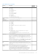
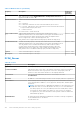
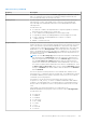

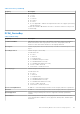
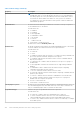
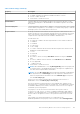
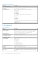
Table Of Contents
- Dell Command | Monitor Version 10.5 Reference Guide
- Contents
- Introduction for Dell Command | Monitor 10.5
- Dell Command | Monitor 10.5 Namespaces
- Profiles for Dell Command | Monitor 10.5
- Classes for Dell Command | Monitor 10.5
- Dell Command | Monitor 10.5 classes and properties
- Classes supported for systems running Linux
- Classes supported for systems running Windows
- DCIM_AlertIndication
- DCIM_ApplicationProxySetting
- DCIM_BaseMetricDefinition
- DCIM_Card
- DCIM_Chassis
- DCIM_Chip
- DCIM_DesktopMonitor
- DCIM_DHCPProtocolEndpoint
- DCIM_EthernetPort
- DCIM_FlatPanel
- DCIM_IPProtocolEndpoint
- DCIM_ImprovementProgramConsent
- DCIM_ControllerView
- DCIM_PhysicalDiskView
- DCIM_VirtualDiskView
- DCIM_PhysicalMemory
- DCIM_PhysicalPackage
- DCIM_ParallelPort
- DCIM_RemoteServiceAccessPoint
- DCIM_Slot
- DCIM_SerialPort
- DCIM_USBPort
- DCIM_Memory
- DCIM_PCIDevice
- DCIM_DisplayController
- DCIM_Fan
- DCIM_IndicatorLED
- DCIM_PowerSupply
- DCIM_Battery
- DCIM_Processor
- DCIM_NumericSensor
- DCIM_Sensor
- DCIM_DeviceBay
- DCIM_VideoHead
- DCIM_Button
- DCIM_LCDPanel
- DCIM_NetworkPortConfigurationService
- DCIM_TimeService
- DCIM_AccountManagementService
- DCIM_RoleBasedAuthorizationService
- DCIM_PowerManagementService
- DCIM_BootService
- DCIM_IPConfigurationService
- DCIM_PowerUtilizationManagementService
- DCIM_BIOSService
- DCIM_SoftwareInstallationService
- DCIM_ComputerSystem
- DCIM_RecordLog
- DCIM_OperatingSystem
- DCIM_SoftwareIdentity
- DCIM_BIOSElement
- DCIM_ConcreteJob
- DCIM_BootSourceSetting
- DCIM_BootConfigSetting
- DCIM_IPAssignmentSettingData
- DCIM_PowerAllocationSettingData
- DCIM_AssetAcquisition
- DCIM_AssetExtendedWarrantyInformation
- DCIM_AssetOwnerInformation
- DCIM_AssetSupportInformation
- DCIM_AssetWarrantyInformation
- DCIM_AssetSystemInformation
- DCIM_ThermalInformation
- DCIM_AMTSettings
- DCIM_ASFSettings
- DCIM_VProSettings
- DCIM_AlertIndicationSettingData
- DCIM_HDDAlertIndicationSettingData
- DCIM_BaseMetricValue
- DCIM_LogEntry
- DCIM_IndicatorLEDCapabilities
- DCIM_ProcessorCapabilities
- DCIM_AccountManagementCapabilities
- DCIM_BootServiceCapabilities
- DCIM_PlatformWatchdogServiceCapabilities
- DCIM_DHCPCapabilities
- DCIM_PowerUtilizationManagementCapabilities
- DCIM_EnabledLogicalElementCapabilities
- DCIM_ButtonCapabilities
- DCIM_LCDPanelCapabilities
- DCIM_PowerManagement
- DCIM_PhysicalAssetCapabilities
- DCIM_RoleBasedManagementCapabilities
- DCIM_AllocationCapabilities
- DCIM_BIOSServiceCapabilities
- DCIM_SoftwareInstallationServiceCapabilities
- DCIM_ConcreteCollection
- DCIM_RedundancySet
- DCIM_Role
- DCIM_IndicationSettingCollection
- DCIM_ConfigurationCapacity
- DCIM_Location
- DCIM_BIOSEnumeration
- DCIM_BIOSPassword
- DCIM_BIOSString
- DCIM_MemoryError
- DCIM_IdentityContext
- DCIM_OrderedComponent
- DCIM_Container
- DCIM_ConcreteComponent
- DCIM_SystemDevice
- DCIM_AccountOnSystem
- DCIM_InstalledOS
- DCIM_SystemBIOS
- DCIM_SystemComponent
- DCIM_SettingsDefineCapabilities
- DCIM_DeviceSAPImplementation
- DCIM_HostedAccessPoint
- DCIM_HostedCollection
- DCIM_HostedService
- DCIM_VideoHeadOnController
- DCIM_SAPSAPDependency
- DCIM_ReferencedProfile
- DCIM_MetricDefForME
- DCIM_MetricForME
- DCIM_MetricInstance
- DCIM_ElementInConnector
- DCIM_Docked
- DCIM_ConcreteDependency
- DCIM_Realizes
- DCIM_ComputerSystemPackage
- DCIM_RunningOS
- DCIM_UseOfLog
- DCIM_AssociatedIndicatorLED
- DCIM_AssociatedCacheMemory
- DCIM_AssociatedSensor
- DCIM_RemoteAccessAvailableToElement
- DCIM_ServiceServiceDependency
- DCIM_DeviceConnection
- DCIM_ElementSoftwareIdentity
- DCIM_ElementCapabilities
- DCIM_ElementSettingData
- DCIM_OrderedMemberOfCollection
- DCIM_MemberOfCollection
- DCIM_OwningCollectionElement
- DCIM_ElementConformsToProfile
- DCIM_RoleLimitedToTarget
- DCIM_ElementCapacity
- DCIM_ServiceAffectsElement
- DCIM_AssociatedPowerManagementService
- DCIM_ServiceAvailableToElement
- DCIM_LogManagesRecord
- DCIM_InstalledSoftwareIdentity
- DCIM_ConcreteIdentity
- DCIM_SMARTAttributeInfo
- DCIM_SettingsDefineState
- DCIM_ElementLocation
- DCIM_CredentialContext
- DCIM_OwningJobElement
- BIOS settings supported in Dell Command | Monitor 10.5
- Alerts in Dell Command | Monitor 10.5
- Sample scripts for Dell Command | Monitor 10.5

Table 31. NumericSensor (continued)
Property Description Supported
Operating
System(s)
● 7 = Switch
● 8 = Lock
● 9 = Humidity
● 10 = Smoke Detection
● 11 = Presence
● 12 = Air Flow
● 13 = Power Consumption
● 14 = Power Production
● 15 = Pressure
● 16 = Intrusion
● .. = DMTF Reserved
● 32768..65535 = Vendor Reserved
SystemCreationClas
sName
The CreationClassName of the scoping system. Windows, Linux
SystemName The System Name of the scoping system. Windows, Linux
TransitioningToStat
e
Indicates the target state to which the instance is transitioning. Possible values are:
● 0 = Unknown
● 2 = Enabled
● 3 = Disabled
● 4 = Shut Down
● 5 = No Change—Indicates that no transition is in progress.
● 6 = Offline
● 7 = Test
● 8 = Defer
● 9 = Quiesce
●
10 = Reboot
● 11 = Reset
● 12 = Not Applicable—Indicates the implementation does not support
representing ongoing transitions.
A value other than 5 or 12 identifies the state to which the element is in the
process of transitioning.
Windows, Linux
UnitModifier The unit multiplier for the values returned by this Sensor. All the values returned
by this Sensor are represented in the units obtained by (BaseUnits * 10 raised to
the power of the UnitModifier). For example, if BaseUnits is Volts and the Unit
Modifier is -6, then the units of the values returned are MicroVolts. However, if the
RateUnits property is set to a value other than None, then the units are further
qualified as rate units.
In the above example, if RateUnits is set to Per Second, then the values returned
by the Sensor are in MicroVolts/Second. The units apply to all numeric properties
of the Sensor, unless explicitly overridden by the Units qualifier.
Windows, Linux
UpperThresholdCriti
cal
The Sensor's threshold values specify the ranges (min and max values) for
determining whether the Sensor is operating under Normal, NonCritical, Critical
conditions. If the CurrentReading is above UpperThresholdCritical, then the Current
State is critical.
Windows, Linux
UpperThresholdNon
Critical
The Sensor's threshold values specify the ranges (min and max
values) for determining whether the Sensor is operating under Normal,
NonCritical or Critical conditions. If the CurrentReading is between
LowerThresholdNonCritical and UpperThresholdNonCritical, then the Sensor is
reporting a normal value. If the CurrentReading is between UpperThreshold
NonCritical and UpperThresholdCritical, then the CurrentState is NonCritical.
Example for Set command: wmic /namespace:\\root\dcim\sysman path
Windows, Linux
Dell Command | Monitor 10.5 classes and properties 121