
Reference Guide
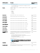

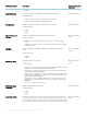

BIOS Settings Name Description Supported Operating
System(s)
• 1 — ADC Input — Sets the channel mode as Analog-to-Digital Converter
(ADC) input.
• 2 — DAC Output — Sets the channel mode as Digital-to-Analog Converter
(DAC) output.
• 3 — DAC and ADC — Sets the channel mode as DAC output, but can be
monitored through ADC input.
• 8 — GPIO — Sets the channel mode as General Purpose Input or Output.
Analog Digital Interface
Mode Channel 2
Sets the dened Analog/Digital Interface mode for channel 2.
Possible values are:
• 0 — Unused — Channel is unused.
• 1 — ADC Input — Sets the channel mode as Analog-to-Digital Converter
(ADC) input.
• 2 — DAC Output — Sets the channel mode as Digital-to-Analog Converter
(DAC) output.
• 3 — DAC and ADC — Sets the channel mode as DAC output, but can be
monitored through ADC input.
• 8 — GPIO — Sets the channel mode as General Purpose Input or Output.
Microsoft Windows,
Linux
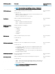
Analog Digital Interface
Mode Channel 3
Sets the dened Analog/Digital Interface mode for channel 3.
Possible values are:
• 0 — Unused — Channel is unused.
• 1 — ADC Input — Sets the channel mode as Analog-to-Digital Converter
(ADC) input.
• 2 — DAC Output — Sets the channel mode as Digital-to-Analog Converter
(DAC) output.
• 3 — DAC and ADC — Sets the channel mode as DAC output, but can be
monitored through ADC input.
• 8 — GPIO — Sets the channel mode as General Purpose Input or Output.
Microsoft Windows,
Linux
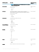
Analog Digital Interface
Mode Channel 4
Sets the dened Analog/Digital Interface mode for channel 4.
Possible values are:
• 0 — Unused — Channel is unused.
• 1 — ADC Input — Sets the channel mode as Analog-to-Digital Converter
(ADC) input.
• 2 — DAC Output — Sets the channel mode as Digital-to-Analog Converter
(DAC) output.
• 3 — DAC and ADC — Sets the channel mode as DAC output, but can be
monitored through ADC input.
• 8 — GPIO — Sets the channel mode as General Purpose Input or Output.
Microsoft Windows,
Linux
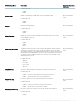
Analog Digital Interface
Mode Channel 5
Sets the dened Analog/Digital Interface mode for channel 5.
Possible values are:
• 0 — Unused — Channel is unused.
• 1 — ADC Input — Sets the channel mode as Analog-to-Digital Converter
(ADC) input.
• 2 — DAC Output — Sets the channel mode as Digital-to-Analog Converter
(DAC) output.
• 3 — DAC and ADC — Sets the channel mode as DAC output, but can be
monitored through ADC input.
• 8 — GPIO — Sets the channel mode as General Purpose Input or Output.
Microsoft Windows,
Linux
BIOS settings supported in Dell Command | Monitor10.1.0 253