
Users Guide

Fabric Management Overview
Fabric management helps avoid electrical, configuration, or connectivity-related problems due to installation of an IOM or MC that has an
incompatible fabric type from the chassis' established fabric type. Invalid hardware configurations can cause electric or functional
problems to the chassis or its components. Fabric management prevents invalid configurations from powering on.
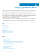
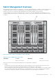
The following figure shows the location of IOMs in the chassis. The location of each IOM is indicated by its group number (A, B, or C).
These discrete fabric paths are split into two IO Banks, bank one and two. On the chassis, the IOM slot names are marked A1, A2, B1, B2,
C1, and C2.
Figure 13. Rear View of a Chassis, Showing the Location of the IOMs
Table 40. Locations of IOMs at the rear of a chassis
IOM number Location IOM number Location
1 Bank 1 (Slots A1, B1, C1) 2 Bank 2 (Slots A2, B2, C2)
CMC creates entries in both the hardware log and CMC logs for invalid hardware configurations.
For example:
• An Ethernet MC connected to a Fibre Channel IOM is an invalid configuration. However, an Ethernet MC connected to both an
Ethernet switch and an Ethernet pass-through IOM installed in the same IOM group is a valid connection.
• A Fibre Channel pass-through IOM and a fibre channel switch IOM in slots B1 and B2 is a valid configuration if the first MCs on all the
servers are also fibre channel. In this case, CMC powers-on the IOMs and the servers. However, certain fibre channel redundancy
software may not support this configuration; not all valid configurations are necessarily supported configurations.
Managing Input Output Fabric
169