
Users Guide
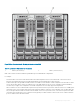
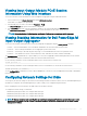
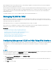

Figure 13. Rear View of a Chassis, Showing the Location of the IOMs
Table 40. Locations of IOMs at the rear of a chassis
1 Bank 1 (Slots A1, B1, C1) 2 Bank 2 (Slots A2, B2, C2)
CMC creates entries in both the hardware log and CMC logs for invalid hardware congurations.
For example:
• An Ethernet MC connected to a Fibre Channel IOM is an invalid conguration. However, an Ethernet MC connected to both an
Ethernet switch and an Ethernet pass-through IOM installed in the same IOM group is a valid connection.
• A Fibre Channel pass-through IOM and a bre channel switch IOM in slots B1 and B2 is a valid conguration if the rst MCs on all the
servers are also bre channel. In this case, CMC powers-on the IOMs and the servers. However, certain bre channel redundancy
software may not support this conguration; not all valid congurations are necessarily supported congurations.
Fabric verication for server IOMs and MCs is performed only when the chassis is powered on. When the chassis is on standby power,
the iDRACs on the server modules remain powered o and thus are unable to report the server's MC fabric type. The MC fabric type
may not be reported in the CMC user interface until the iDRAC on the server is powered on. Also, if the chassis is powered on, fabric
verication is performed when a server or IOM is inserted (optional). If a fabric mismatch is detected, the server or IOM is allowed to
power on and the status LED ashes Amber.
Managing Input Output Fabric
193