
Users Guide
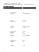

Component LED Color, Blinking Pattern Status
Green, dark Powered o
Blue, glowing steadily Normal
Blue, blinking User-enabled module identier
Amber, glowing steadily Not used
Amber, blinking Fault
Blue, dark No fault
Fan Green, glowing steadily Fan working
Green, blinking Not used
Green, dark Powered o
Amber, glowing steadily Fan type not recognized, update CMC rmware
Amber, blinking Fan fault; tachometer out of range
Amber, dark Not used
PSU (Oval) Green, glowing steadily AC OK
(Oval) Green, blinking Not used
(Oval) Green, dark AC Not OK
Amber, glowing steadily Not used
Amber, blinking Fault
Amber, dark No fault
(Circle) Green, glowing steadily DC OK
(Circle) Green, dark DC Not OK
Troubleshooting Non-responsive CMC
If you cannot log in to CMC using any of the interfaces (the Web interface, Telnet, SSH, remote RACADM, or serial), you can verify
the CMC functionality observing the LEDs on CMC, obtaining recovery information using the DB-9 serial port, or recovering the
CMC rmware image.
NOTE: It is not possible to log in to the standby CMC using a serial console.
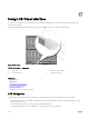
Observing LEDs to Isolate the Problem
Facing the front of CMC as it is installed in the chassis, there are two LEDs on the left side of the card:
• Top LED — The top green LED indicates power. If it is not on:
– Verify that you have AC present to at least one power supply.
– Verify that the CMC card is seated properly. You can release or pull the ejector handle, remove the CMC, reinstall the CMC
making sure that the board is inserted all the way and the latch closes correctly.
• Bottom LED — The bottom LED is multi-colored. When CMC is active and running, and there are no problems, the bottom LED
is blue. If it is amber, a fault is detected. The fault may be caused by any of the following three events:
– A core failure. In this case, the CMC board must be replaced.
– A self-test failure. In this case, the CMC board must be replaced.
– An image corruption. In this case, upload the CMC rmware image to recover the CMC.
216