
Users Guide


NOTE: Do not turn on the servers.
6. Using the LCD panel on the front of the system, provide CMC with a static IP address or configure it
for DHCP.
7. Connect to the CMC IP address and provide default username (root) and password (calvin).
8. Provide each iDRAC with an IP address in the CMC Web interface and enable the LAN and IPMI
interface.
NOTE: iDRAC LAN interface on some servers are disabled by default.
9. Provide each I/O module with an IP address in the CMC Web interface.
10. Connect to each iDRAC and provide final configuration of iDRAC. Default user name is root and
password is calvin.
11. Connect to each I/O module through the Web browser and provide final configuration of the I/O
module.
12. Turn on the servers and install the operating system.
Basic CMC Network Connection
CAUTION: Connecting the STK port to the management network can have unpredictable results.
Cabling GB and STK to the same network (broadcast domain) can cause a broadcast storm.
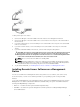
For the highest degree of redundancy, connect each available CMC to your management network.
Each CMC has two RJ-45 Ethernet ports, labeled GB (the uplink port) and STK (the stacking or cable
consolidation port). With basic cabling, you connect the GB port to the management network and leave
the STK port unused.
Daisy chain CMC Network Connection
If you have multiple chassis in a rack, you can reduce the number of connections to the management
network by daisy-chaining up to four chassis together. If each of the four chassis contains a redundant
CMC, by daisy-chaining you can reduce the number of management network connections required from
eight to two. If each chassis has only one CMC, you can reduce the connections required from four to
one.
When daisy-chaining chassis together, GB is the uplink port and STK is the stacking (cable consolidation)
port. Connect the GB ports to the management network or to the STK port of CMC in a chassis that is
closer to the network. You must connect the STK port only to a GB port further from the chain or
network.
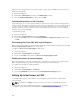
Create separate chains for CMCs in the active CMC slot and the second CMC slot.
The following figure illustrates the arrangement of cables for four daisy-chained chassis, each with active
and standby CMCs.
25