
Deployment Guide
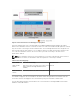
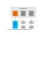
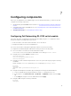
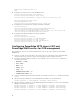
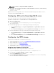

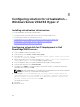

Figure 2. Network architecture for VRTX Hyper-V deployment
In the preceding design, each of the Dell Blade server LOMs (LAN On Motherboard) directly maps to
Fabric A. The mezzanine cards on slot B and slot C are not used for the traditional I/O expansion. Instead,
they are used for connecting to the PCIe infrastructure. The PowerEdge VRTX chassis is designed to use
PCIe slots through two PCIe switches–one for Fabric B and one for Fabric C. Each PCIe switch ties into
one of the two mezzanine cards on the server nodes to provide connectivity to the PCIe slot as
mentioned in Table 6.
NOTE: The mezzanine cards on the slots B and C are not used for network traffic in this reference
architecture. However, the mezzanine cards are required for connectivity to SPERC.
Table 6. PCIe switch mappings
PCIe switch PCIe slot connectivity Mezzanine slot
Fabric B PCIe
Switch
PCIe slot 3, PCIe slot 6, PCIe slot 7, PCIe slot 8
and a Shared PowerEdge RAID Controller
(SPERC)
Mezz B
Fabric C PCIe
Switch
PCIe slot 1, PCIe slot 2, PCIe slot 4, PCIe slot 5 Mezz C
The SPERC is mapped to the server blades in the VRTX chassis through Fabrics B and C PCIe switches.
These PCIe switches are mapped to the server blades by using the mezzanine cards B and C.
The following figure illustrates how the fabrics are connected in the PowerEdge M630 server and the
utilization of the I/O modules.
11