
Users Guide
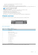
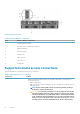
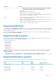
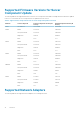
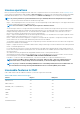
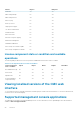

Figure 2. Chassis front panel
Table 2. Chassis front panel — components
Item Indicator, Button, or Connector
1
System identification button
2
Enclosure power-on indicator, power button
3
Diagnostic indicators
4
KVM select button
5
Compute sled
6
Video connector
7
USB connector
8
Storage sled
Supported remote access connections
The following table lists the supported remote access connections.
Table 3. Supported remote access connections
Connection Features
CMC Network Interface ports
• Gb ports: Dedicated network interface for the CMC web interface. The CMC has two
RJ-45 Ethernet ports:
• Gb1 (the uplink port)
• Gb2 (the stacking or cable consolidation port). The STK/Gb2 port can also be used for
CMC NIC failover.
NOTE: Ensure that the CMC setting is changed from default Stacking to
Redundant to implement NIC failover.
CAUTION: Connecting the STK/Gb2 port to the management network will
have unpredictable results if the CMC setting is not changed from default
Stacking to Redundant, to implement NIC failover. In the default Stacking
mode, cabling the Gb1 and STK/Gb2 ports to the same network (broadcast
domain) can cause a broadcast storm. A broadcast storm can also occur if
the CMC setting is changed to Redundant mode, but the cabling is daisy
14 Overview