
Users Guide

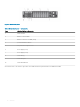
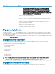
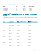

Figure 2. Chassis front panel
Table 2. Chassis front panel — components
Item Indicator, Button, or Connector
1
System identication button
2
Enclosure power-on indicator, power button
3
Diagnostic indicators
4
KVM select button
5
Compute sled
6
Video connector
7
USB connector
8
Storage sled
Supported remote access connections
The following table lists the supported remote access connections.
Table 3. Supported remote access connections
Connection Features
CMC Network Interface ports
• Gb ports: Dedicated network interface for the CMC web interface. The CMC has two
RJ-45 Ethernet ports:
– Gb1 (the uplink port)
– Gb2 (the stacking or cable consolidation port). The STK/Gb2 port can also be used for
CMC NIC failover.
NOTE: Ensure that the CMC setting is changed from default Stacking to
Redundant to implement NIC failover.
Overview 15