
Users Guide

You can also check the ntpd status by typing the following racadm command:
racadm getractime –n
If the ‘*’ is not displayed for one of the congured servers, the settings may not be congured correctly. The output of this
command contains detailed NTP statistics that may be useful in debugging the problem.
If you attempt to congure a Windows-based NTP server, it may help to increase the MaxDist parameter for ntpd. Before
changing this parameter, understand all the implications, since the default setting must be large enough to work with most NTP
servers.
To modify the parameter, type the following command:
racadm config –g cfgRemoteHosts –o cfgRhostsNtpMaxDist 32
After making the change, disable NTP, wait for 5-10 seconds, then enable NTP again:
NOTE: NTP may take an additional three minutes to synchronize again.
To disable NTP, type:
racadm config –g cfgRemoteHosts –o cfgRhostsNtpEnable 0
To enable NTP, type:
racadm config –g cfgRemoteHosts –o cfgRhostsNtpEnable 1
If the NTP servers are congured correctly and this entry is present in the trace log, then this conrms that CMC is not able to
synchronize with any of the congured NTP servers.
If the NTP server IP address is not congured, you may see a trace log entry similar to the following:
Jan 8 19:59:24 cmc ntpd[1423]: Cannot find existing interface for address 1.2.3.4 Jan 8
19:59:24 cmc ntpd[1423]: configuration of 1.2.3.4 failed
If an NTP server setting was congured with an invalid host name, you may see a trace log entry as follows:
Aug 21 14:34:27 cmc ntpd_initres[1298]: host name not found: blabla Aug 21 14:34:27 cmc
ntpd_initres[1298]: couldn't resolve `blabla', giving up on it
For information on how to enter the gettracelog command to review the trace log using the CMC Web interface, see Using
Diagnostic Console.
Interpreting LED colors and blinking patterns
The LEDs on the chassis provide the following status of a component:
• A blinking amber LED on a module indicates a fault on that module.
• Blue, blinking LEDs are congurable by the user and used for identication. For more information about conguration, see
CMC_Stmp_Conguring LEDs to Identify Components on the Chassis.
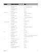
Table 33. LED Color and Blinking Patterns
Component LED Color, Blinking Pattern Status
CMC Turned on
Firmware is being uploaded
Turned o
Blue, glowing steadily Active
Blue, blinking User-enabled module identier
Amber, glowing steadily Not used
Amber, blinking Fault
Server Turned on
Firmware is being uploaded
146