
Users Guide
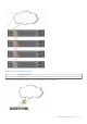

Table Of Contents
- Dell Chassis Management Controller Version 2.0 for PowerEdge FX2 and FX2s User's Guide
- Contents
- Overview
- Key Features
- Chassis overview
- Supported remote access connections
- Supported platforms
- Supported web browsers
- Supported firmware versions
- Supported Firmware Versions for Server Component Update
- Supported Network Adapters
- Managing licenses
- Viewing localized versions of the CMC web interface
- Supported management console applications
- How to use this Guide
- Other documents you may need
- Accessing support content from the Dell EMC support site
- Installing and setting up CMC
- Installing CMC hardware
- Checklist to set up chassis
- Daisy chain FX2 CMC network connection
- Using remote access software from a management station
- Remote RACADM installation
- Installing remote RACADM on a Windows management station
- Installing remote RACADM on a Linux management station
- Uninstalling remote RACADM from a Linux management station
- Configuring a web browser
- Downloading and updating CMC firmware
- Setting chassis physical location and chassis name
- Setting date and time on CMC
- Configuring LEDs to identify components on the chassis
- Configuring CMC properties
- Configuring front panel
- Configuring chassis management at server mode
- Installing CMC hardware
- Logging into CMC
- Configure public key authentication over SSH
- Accessing CMC web interface
- Logging into CMC as a local user, active directory user, or LDAP user
- Logging into CMC using a smart card
- Logging into CMC using Single Sign-On
- Logging into CMC using serial, Telnet, or SSH console
- Logging into CMC using public key authentication
- Multiple CMC sessions
- Updating firmware
- Signed CMC firmware image
- Downloading CMC firmware
- Viewing currently installed firmware versions
- Updating the CMC firmware
- Updating the CMC using DUP
- Updating chassis infrastructure firmware
- Updating server iDRAC firmware
- Updating server iDRAC firmware using web interface
- Updating server component firmware
- Enabling Lifecycle Controller
- Choosing server component firmware update type using CMC web interface
- Filtering components for firmware updates
- Viewing firmware inventory
- Saving chassis inventory report using CMC web interface
- Configuring network share using CMC web interface
- Lifecycle Controller job operations
- Reinstalling server component firmware
- Rolling back server component firmware
- Upgrading server component firmware
- Upgrading server component firmware from file using CMC web interface
- Server component single click update using network share
- Pre-requisites for using network share update mode
- Upgrading server component firmware from network share using CMC web interface
- Deleting Scheduled Server Component Firmware Jobs
- Recovering iDRAC firmware using CMC
- Viewing chassis information and monitoring chassis and component health
- Viewing chassis and component summaries
- Viewing chassis summary
- Viewing chassis controller information and status
- Viewing information and health status of all servers
- Viewing information and health status of storage sleds
- Viewing information and health status of the IOMs
- Viewing information and health status of fans
- Viewing front panel properties
- Viewing KVM information and health status
- Viewing information and health status of temperature sensors
- Configuring CMC
- Enabling or disabling DHCP for the CMC Network Interface Address
- Enabling or disabling DHCP for DNS IP addresses
- Setting static DNS IP addresses
- Viewing and modifying CMC network LAN settings
- Configuring IPv4 and IPv6 DNS settings
- Configuring auto negotiation, duplex mode, and network speed for IPv4 and IPv6
- Configuring Management Port 2
- Configuring Management Port 2 using RACADM
- Federal Information Processing Standards
- Configuring services
- Configuring CMC extended storage card
- Setting up Chassis Group
- Adding members to Chassis Group
- Removing a member from the leader
- Disbanding a Chassis Group
- Disabling an individual Member at the Member chassis
- Launching the web page of a Member chassis or server
- Propagating Leader chassis properties to Member chassis
- Synchronizing a new Member with Leader chassis properties
- Server inventory for MCM group
- Saving server inventory report
- Chassis Configuration Profiles
- Saving Chassis Configuration
- Restoring Chassis Configuration Profile
- Viewing Stored Chassis Configuration Profiles
- Importing Chassis Configuration Profiles
- Applying Chassis Configuration Profiles
- Exporting Chassis Configuration Profiles
- Editing Chassis Configuration Profiles
- Deleting Chassis Configuration Profiles
- Configuring Multiple CMCs through RACADM Using Chassis Configuration Profiles
- Configuring multiple CMCs using RACADM
- Configuring servers
- Configuring slot names
- Configuring iDRAC network settings
- Configuring iDRAC QuickDeploy network settings
- QuickDeploy IP address assignments for servers
- Modifying iDRAC Network Settings for individual server iDRAC
- Modifying iDRAC network settings using RACADM
- Configuring iDRAC VLAN tag settings
- Configuring iDRAC VLAN tag settings using web interface
- Configuring iDRAC VLAN tag settings using RACADM
- Setting first boot device
- Configuring sled network uplink
- Deploying remote file share
- Configuring server FlexAddress
- Configuring profile settings using server configuration replication
- Accessing Profile page
- Managing stored profiles
- Adding or saving profile
- Applying profile
- Importing profile
- Exporting profile
- Editing profile
- Viewing profile settings
- Viewing stored profile settings
- Viewing profile log
- Completion status and troubleshooting
- Quick Deploy of profiles
- Assigning server profiles to slots
- Boot Identity Profiles
- Saving Boot Identity Profiles
- Applying Boot Identity Profiles
- Clearing Boot Identity Profiles
- Viewing Stored Boot Identity Profiles
- Importing Boot Identity Profiles
- Exporting Boot Identity Profiles
- Deleting Boot Identity Profiles
- Managing Virtual MAC Address Pool
- Creating MAC Pool
- Adding MAC Addresses
- Removing MAC Addresses
- Deactivating MAC Addresses
- Launching iDRAC using Single Sign-On
- Launching remote console from server status page
- Configuring storage sleds
- Configuring CMC to send alerts
- Configuring user accounts and privileges
- Configuring CMC for Single Sign-On or Smart Card login
- System requirements
- Prerequisites for Single Sign-On or Smart Card login
- Generating Kerberos keytab file
- Configuring CMC for Active Directory schema
- Configuring browser for SSO login
- Configuring browser for Smart Card login
- Configuring CMC SSO login or Smart Card login for Active Directory users using RACADM
- Configuring CMC SSO Or Smart Card Login For Active Directory Users Using Web Interface
- Uploading Keytab file
- Configuring CMC SSO login or Smart Card login for Active Directory users using RACADM
- Configuring CMC to use Command Line consoles
- Using FlexAddress and FlexAddress Plus cards
- About FlexAddress
- Configuring FlexAddress
- Command messages
- FlexAddress DELL SOFTWARE LICENSE AGREEMENT
- Viewing WWN or MAC address information
- Viewing basic WWN or MAC address information using web interface
- Viewing advanced WWN or MAC address information using web interface
- Viewing WWN or MAC address information using RACADM
- Managing Fabrics
- Monitoring IOM health
- Configuring network settings for IOM
- Viewing Input Output module uplink and downlink status using web interface
- Viewing Input Output module FCoE session information using web interface
- Resetting IOM to factory default settings
- Updating IOM software using CMC web interface
- IOA or MXL GUI
- Input Output Aggregator Module
- Using VLAN Manager
- Assigning VLAN to IOM
- Configuring VLAN settings on IOMs using CMC web interface
- Viewing the VLAN settings on IOMs using CMC web interface
- Viewing the current VLAN settings on IOMs using CMC web interface
- Removing VLANs for IOMs using CMC web interface
- Updating untagged VLANs for IOMs using CMC web interface
- Resetting VLANs for IOMs using CMC web interface
- Managing and monitoring power
- Redundancy policies
- Default Redundancy configuration
- Multi-node sled adaptation
- Chassis power limit monitoring
- Viewing power consumption status
- Viewing power budget status using CMC web interface
- Viewing power budget status using RACADM
- Redundancy status and overall power health
- Configuring PCIe slots
- Troubleshooting and recovery
- Gathering configuration information, chassis status, and logs using RACDUMP
- Supported interfaces
- Downloading SNMP Management Information Base file
- First steps to troubleshoot a remote system
- Troubleshooting Alerts
- Viewing Event Logs
- Using Diagnostic Console
- Resetting Components
- Saving or Restoring Chassis Configuration
- Troubleshooting Network Time Protocol Errors
- Interpreting LED colors and blinking patterns
- Troubleshooting Network Problems
- General troubleshooting
- Resetting Forgotten Administrator Password
- Gathering configuration information, chassis status, and logs using RACDUMP
- Frequently asked questions

You can also power on the chassis using the command line interface, use racadm chassisaction powerup command
to accomplish it.
NOTE: Do not turn on the servers.
7. The default CMC network configuration is Static with the CMC IP address 192.168.0.120. If you want to change the network
configuration to DHCP, connect a serial cable to serial port on the CMC. For more information on serial connection, refer to
Serial interface/protocol setup in Using Remote Access Software From a Management Station section.
After the serial connection is established, login and use the command racadm setniccfg —d to change the network
configuration to DHCP. CMC takes 30 to 60 seconds approximately to obtain the IP address from the DHCP server.
To view the DHCP assigned CMC IP address, use one of the following methods:
● To view CMC IP address using serial connection with CMC, perform the following steps:
a. Connect one end of the serial null modem cable to the serial connector on the back of the chassis.
b. Connect the other end of the cable to the management system serial port.
c. After the connection is established, login to CMC using default root account credentials.
d. Run the racadm getniccfg command.
In the output displayed, search for Current IP Address.
● To view CMC IP address by connecting the server using KVM, perform the following steps:
a. Connect to a server in the chassis using KVM.
NOTE: For more details on how to connect a server through KVM, see Accessing Server Using KVM.
b. Turn on the server.
c. Make sure the server is set to boot in Unified Extensible Firmware Interface (UEFI) mode.
d. Press F2 to access the System Setup page.
e. In the System Setup page, click iDRAC Settings > System Summary.
The CMC IP address is displayed in the Chassis Management Controller section.
For more information about iDRAC Settings page in the iDRAC GUI, see the Dell Integrated Dell Remote Access
Controller (iDRAC) User’s Guide .
8. Connect to the CMC IP address by using a web browser by typing the default root account credential.
9. Configure iDRAC network settings as required. by default, iDRAC LAN is enabled with static IP configured. To determine the
default static IP address with an Enterprise license, go to Server Overview > Setup > iDRAC. You can also determine
the static IP address with an Express license. Go to Server Overview > Server-Slot > Setup > iDRAC.
10. Provide the IO module with an external management IP address(if applicable) in the CMC web interface. You can get the IP
address by clicking I/O Module Overview, and then clicking Setup.
11. Connect to each iDRAC through the web interface using default root account credential to complete any necessary
configuration.
12. Turn on the servers and install the operating system.
NOTE: The default local account credential is root (user name) and calvin (user password).
Daisy chain FX2 CMC network connection
If you have multiple chassis in a rack, you can reduce the number of connections to the management network by daisy-chaining
up to ten chassis together. You can reduce the number of management network uplink connections required from ten to one.
When daisy-chaining chassis together, GB is the uplink port and STK is the stacking (cable consolidation) port. Connect the Gb
ports to the management network or to the STK port of CMC in a chassis that is closer to the network. Connect the STK port
only to a Gb port further from the chain or network.
The following figure illustrates the arrangement of cables for four daisy-chained chassis, each with active CMCs.
24
Installing and setting up CMC