
Users Guide
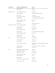
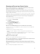

Component LED Color, Blinking Pattern Status
PCI Blue, dark Turned On
Blue, blinking PCI identification is in progress.
Amber, blinking Fault
Troubleshooting Non-responsive CMC
If you cannot log in to CMC using any of the interfaces (the web interface, Telnet, SSH, remote RACADM,
or serial), you can verify the CMC functionality observing the LEDs on CMC, obtaining recovery
information using the DB-9 serial port, or recovering the CMC firmware image.
Observing LEDs to Isolate the Problem
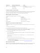
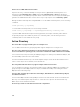
The CMC has an LED which changes color to indicate:
Color
Description
Blue Normal operation
Blue, blinking ID (0.5 second on, 0.5 second off)
Amber Chassis fault summary
Amber, blinking Chassis fault with concurrent ID
Obtain Recovery Information from DB-9 Serial Port
If the CMC LED is amber, recovery information is available from the DB-9 serial port located on the front
of CMC.
To obtain recovery information:
1. Install a NULL modem cable between a CMC system and a client system.
2. Open a terminal emulator of your choice (such as HyperTerminal or Minicom). Enter the following
specification when prompted: 8 bits, no parity, no flow control, baud rate 115200.
A core memory failure displays an error message every 5 seconds.
3. Press the <Enter> key.
If a recovery prompt appears, additional information is available. The prompt indicates the CMC slot
number and failure type.
To display failure reason and syntax for a few commands, type recover, and then press <Enter>.
Sample prompts:
recover1[self test] CMC self test failure
recover1[Bad FW images] CMC has corrupted images
• If the prompt indicates a self test failure, there are no serviceable components on CMC. CMC is
bad and must be returned to Dell.
• If the prompt indicates Bad FW Images, complete tasks in Recovering Firmware Image1.
Recovering Firmware Image
CMC enters recover mode when a normal CMC operating boot is not possible. In recover mode, a small
subset of commands are available that allow you to reprogram the flash devices by uploading the
156