
Users Guide
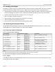
Table Of Contents
- Table of Contents
- 1 Regulatory and Safety Approvals
- 2 Functional Description
- 3 Network Link and Activity Indication
- 4 Features
- 4.1 Software and Hardware Features
- 4.2 Virtualization Features
- 4.3 VXLAN
- 4.4 NVGRE/GRE/IP-in-IP/Geneve
- 4.5 Stateless Offloads
- 4.6 Priority Flow Control
- 4.7 Virtualization Offload
- 4.8 SR-IOV
- 4.9 Network Partitioning (NPAR)
- 4.10 Security
- 4.11 RDMA over Converged Ethernet – RoCE
- 4.12 VMWare Enhanced Networking Stack (ENS)
- 4.13 Supported Combinations
- 4.14 Unsupported Combinations
- 5 Installing the Hardware
- 6 Software Packages and Installation
- 7 Updating the Firmware
- 8 Link Aggregation
- 9 System-Level Configuration
- 10 PXE Boot
- 11 SR-IOV – Configuration and Use Case Examples
- 12 NPAR – Configuration and Use Case Example
- 13 Tunneling Configuration Examples
- 14 RoCE – Configuration and Use Case Examples
- 15 DCBX – Data Center Bridging
- 16 DPDK – Configuration and Use Case Examples
- Revision History

Broadcom NetXtreme-E-UG304-2CS
43
NetXtreme-E User Guide User Guide for Dell Platforms
5.3 Installing the Adapter
The following instructions apply to installing the Broadcom NetXtreme-E Ethernet adapter (add-in NIC) into most servers.
See the manuals that are supplied with the server for details about performing these tasks on this particular server.
1. Review the Safety Precautions and Preinstallation Checklist before installing the adapter. Ensure that the system power
is OFF and unplugged from the power outlet, and that proper electrical grounding procedures have been followed.
2. Open the system case and select any empty PCIe 3 or 4 x8 or x16 slot.
3. Remove the blank cover plate from the slot.
4. Align the adapter connector edge with the connector slot in the system.
5. Secure the adapter with the adapter clip or screw.
6. Close the system case and disconnect any personal antistatic devices.
5.4 Connecting the Network Cables
The Broadcom NetXtreme-E adapters support SFP+/SFP28/QSFP28/QSFP56 cables with speeds up to 200 Gb/s. The
following tables list the cables supported by the various network adapters.
5.4.1 Supported Cables and Modules
5.4.1.1 Copper
The BCM957416AXXXX and BCM957416XXXX adapters have two RJ-45 connectors used for attaching the system to a
CAT 6E Ethernet copper-wire segment.
Table 21: Supported Cables and Modules
Optical Module Dell Part Number Adapters Description
Methode DM7051 PGYJT BCM957412X,
BCM957414X
SFP+ To 10GBASE-T Transceiver
FTLX1471D3BCL-FC RN84N BCM957412X,
BCM957414X
25 Gb/s SFP28 Transceiver
FTLX8574D3BNL N8TDR BCM957412X,
BCM957414X
85°C extended temperature range
10 Gb/s SFP+ Transceiver
FTLF8536P4BNL-FC HHHHC BCM957412X,
BCM957414X
85°C extended temperature range
10 Gb/s SFP+ Transceiver
FTLX8574D3BCL-FC or
PLRXPLSCS43811
WTRD1 BCM957412X,
BCM957414X
10 Gb/s-SR SFP+ Transceiver
SFP+ to 1000BASE-T Tranceiver XTY28 BCM957412X,
BCM957414X
SFP+ to 1000BASE-T Tranceiver
SFP+ to 10GBASE-T Tranceiver PGYJT BCM957412X,
BCM957414X
SFP+ to 10GBASE-T Tranceiver
NOTE:
1. Direct Attach Cables (DAC) that conform to IEEE standards can be connected to the adapter.
2. Dell part HHHHC and N8TDR are required for the BCM957414M4140D.