
Users Guide


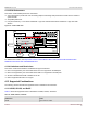
Table Of Contents
- Table of Contents
- 1 Regulatory and Safety Approvals
- 2 Functional Description
- 3 Network Link and Activity Indication
- 4 Features
- 4.1 Software and Hardware Features
- 4.2 Virtualization Features
- 4.3 VXLAN
- 4.4 NVGRE/GRE/IP-in-IP/Geneve
- 4.5 Stateless Offloads
- 4.6 Priority Flow Control
- 4.7 Virtualization Offload
- 4.8 SR-IOV
- 4.9 Network Partitioning (NPAR)
- 4.10 Security
- 4.11 RDMA over Converged Ethernet – RoCE
- 4.12 VMWare Enhanced Networking Stack (ENS)
- 4.13 Supported Combinations
- 4.14 Unsupported Combinations
- 5 Installing the Hardware
- 6 Software Packages and Installation
- 7 Updating the Firmware
- 8 Link Aggregation
- 9 System-Level Configuration
- 10 PXE Boot
- 11 SR-IOV – Configuration and Use Case Examples
- 12 NPAR – Configuration and Use Case Example
- 13 Tunneling Configuration Examples
- 14 RoCE – Configuration and Use Case Examples
- 15 DCBX – Data Center Bridging
- 16 DPDK – Configuration and Use Case Examples
- Revision History

Broadcom NetXtreme-E-UG304-2CS
33
NetXtreme-E User Guide User Guide for Dell Platforms
The NetXtreme-E family of Ethernet controllers support Network Overlays or Tunneling, specifically VXLAN, variants of
GRE, and IP-in-IP. Both VXLAN and NVGRE are defined to support larger scale than basic IEEE 802.1Q VLANs, using a
24-bit label space rather than 12-bit VID. Both are L2-in-L3 tunneling methods with NVGRE using GRE to carry the tunnel
label and VXLAN using UDP to identify the tunnel label.
Stateless offload for tunneling and encapsulated frames in the NetXtreme-E applies to VXLAN, Geneve, L2GRE, NVGRE,
and also IP-in-IP scheme. The section below describes VXLAN as an example to discuss the general support for this feature.
The difference between different tunneling/encapsulation schemes is noted when it is applicable.
All the offloads described in this section are supported on both physical and virtual functions. (PFs and VFs).
4.7.4.1 VXLAN
A Virtual eXtensible Local Area Network (VXLAN), defined in IETF RFC 7348, is used to address the need for overlay
networks within virtualized data centers accommodating multiple tenants. The VXLAN scheme and related protocols are
defined in IETF RFC 7348.
VXLAN is a Layer 2 overlay or tunneling scheme over a Layer 3 network. Each overlay is termed a VXLAN segment. Only
VMs within the same VXLAN segment can communicate with each other. Each VXLAN segment is scoped through a 24-bit
segment ID, VXLAN Network Identifier (VNI). This allows up to 16M VXLAN segments to coexist within the same
administrative domain. The UDP destination port identifies the presence of a VXLAN tunnel.
A VXLAN frame includes the fields described as follows:
Outer Ethernet header:
– Outer Destination MAC Address (DMAC).
– Outer Source MAC Address (SMAC).
– Outer EtherType.
– Optional IEEE 801.Q Tag.
Outer IPv4 Header or IPv6 header (without any IPv6 extension headers) that includes outer destination IP address,
outer source IP address, and protocol. In the case of VXLAN protocol indicates UDP. In the case of L2GRE/NVGRE,
the protocol is GRE. For IP-in-IP, the protocol indicates IP.
Outer UDP header that includes outer destination port and outer source port.
VXLAN header (GRE header, in the case of GRE frames).
Inner Ethernet header:
– Inner Destination MAC Address (DMAC).
– Inner Source MAC Address (SMAC).
– Inner EtherType.
– Optional IEEE 801.Q Tag.
Inner IP header (IPv4 or IPv6) that includes inner destination IP address, inner IP address, and protocol (that indicates
UDP or TCP).
Inner UDP datagram or TCP segment.
4.7.4.2 GRE and NVGRE
The NetXtreme-E family of Ethernet controllers support Generic Routing Encapsulation (GRE) per RFC 2784 and RFC 2890.
Network Virtualization using GRE (NVGRE) is a Layer 2 overlay, used to address the need for overlay networks. As with the
VXLAN scheme, each NVGRE segment is scoped through a 24-bit identifier, called Virtual Subnet Identifier (VSID).