
Users Guide
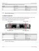
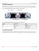
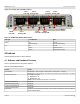
Table Of Contents
- Table of Contents
- 1 Regulatory and Safety Approvals
- 2 Functional Description
- 3 Network Link and Activity Indication
- 4 Features
- 4.1 Software and Hardware Features
- 4.2 Virtualization Features
- 4.3 VXLAN
- 4.4 NVGRE/GRE/IP-in-IP/Geneve
- 4.5 Stateless Offloads
- 4.6 Priority Flow Control
- 4.7 Virtualization Offload
- 4.8 SR-IOV
- 4.9 Network Partitioning (NPAR)
- 4.10 Security
- 4.11 RDMA over Converged Ethernet – RoCE
- 4.12 VMWare Enhanced Networking Stack (ENS)
- 4.13 Supported Combinations
- 4.14 Unsupported Combinations
- 5 Installing the Hardware
- 6 Software Packages and Installation
- 7 Updating the Firmware
- 8 Link Aggregation
- 9 System-Level Configuration
- 10 PXE Boot
- 11 SR-IOV – Configuration and Use Case Examples
- 12 NPAR – Configuration and Use Case Example
- 13 Tunneling Configuration Examples
- 14 RoCE – Configuration and Use Case Examples
- 15 DCBX – Data Center Bridging
- 16 DPDK – Configuration and Use Case Examples
- Revision History

Broadcom NetXtreme-E-UG304-2CS
30
NetXtreme-E User Guide User Guide for Dell Platforms
4.3 VXLAN
A Virtual eXtensible Local Area Network (VXLAN), defined in IETF RFC 7348, is used to address the need for overlay
networks within virtualized data centers accommodating multiple tenants. VXLAN is a Layer 2 overlay or tunneling scheme
over a Layer 3 network. Only VMs within the same VXLAN segment can communicate with each other.
4.4 NVGRE/GRE/IP-in-IP/Geneve
Network Virtualization using GRE (NVGRE), defined in IETF RFC 7637, is similar to a VXLAN.
NOTE: Checksum offload must be enabled when using NVGRE.
4.5 Stateless Offloads
4.5.1 IP, TCP, UDP Checksum Offload
Host software can configure the Ethernet controller to calculate IP, TCP, and UDP checksums as described in RFC 791, RFC
793, and RFC 768 respectively. The first step in checksum calculation is determining the start of an IP and UDP datagram
and TCP segment within a frame, which could vary depending on whether the frame is tagged (VLAN) or encapsulated with
an LLC/SNAP header. Then the checksum is computed from the start to the end of the datagram and inserted into the
appropriate location in the protocol header. The Ethernet controller is designed to support checksum calculation on all frame
types and also on IP datagram and TCP segments containing options.
4.5.2 UDP Fragmentation Offload
UDP Fragmentation Offload (UFO) is a feature that enables the software stack to offload fragmentation of large UDP/IP
datagrams into multiple UDP/IP packets of size suitable for transmission. Enabling UFO can result in reduced CPU load for
UDP applications. Support for this feature is only available in the Linux environment.
4.5.3 TCP Segmentation Offload and Large Send Offload
Large Segment Offload (LSO) is a feature that enables the software stack to offload segmentation of large TCP messages
into multiple TCP/IP packets of size suitable for transmission. Enabling LSO can result in reduced CPU load for TCP
applications. This is also called TCP Segmentation Offload (TSO).
4.5.4 Generic Receive Offload (GRO) and Large Receive Offload (LRO)
Generic Receive Offload (GRO) and Large Receive Offload (LRO) are hardware acceleration for TCP data reception. Both
GRO and LRO modes of TCP receive offload are supported by the Ethernet Controller's Transparent Packet Aggregation
(TPA) feature. Enabling GRO and LRO can significantly reduce CPU load and increase throughput for TCP applications by
reducing the number of received messages, interrupts, and DMA operations.
TPA aggregates TCP streams by managing context entries. Each entry in the TPA context is identified by the 4-tuple: Source
IP, destination IP, source TCP port, and destination TCP port.
GRO is the preferred TPA mode as packet boundaries are preserved for network routing applications, which may enable
LSO for transmission.