
Users Guide
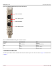
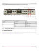
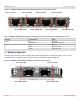
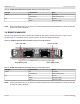
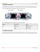
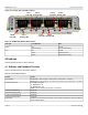
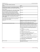
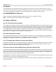
Table Of Contents
- Table of Contents
- 1 Regulatory and Safety Approvals
- 2 Functional Description
- 3 Network Link and Activity Indication
- 4 Features
- 4.1 Software and Hardware Features
- 4.2 Virtualization Features
- 4.3 VXLAN
- 4.4 NVGRE/GRE/IP-in-IP/Geneve
- 4.5 Stateless Offloads
- 4.6 Priority Flow Control
- 4.7 Virtualization Offload
- 4.8 SR-IOV
- 4.9 Network Partitioning (NPAR)
- 4.10 Security
- 4.11 RDMA over Converged Ethernet – RoCE
- 4.12 VMWare Enhanced Networking Stack (ENS)
- 4.13 Supported Combinations
- 4.14 Unsupported Combinations
- 5 Installing the Hardware
- 6 Software Packages and Installation
- 7 Updating the Firmware
- 8 Link Aggregation
- 9 System-Level Configuration
- 10 PXE Boot
- 11 SR-IOV – Configuration and Use Case Examples
- 12 NPAR – Configuration and Use Case Example
- 13 Tunneling Configuration Examples
- 14 RoCE – Configuration and Use Case Examples
- 15 DCBX – Data Center Bridging
- 16 DPDK – Configuration and Use Case Examples
- Revision History

Broadcom NetXtreme-E-UG304-2CS
26
NetXtreme-E User Guide User Guide for Dell Platforms
3.9 BCM957416N4160DC
Each Ethernet interface has a link LED to indicate Link status and an activity LED to indicate data traffic. The LEDs are
shown in Figure 20 and described Table 14. Its locations and form factors conform to the OCP 3.0 Design Specification.
Figure 20: BCM957416N4160DC Network Adapter Activity and Link LED Locations
3.10 BCM957504-N425D
The SFP28 port supports two LEDs to indicate traffic activities and link speed. The LEDs are visible as shown in Figure 21.
Its locations and form factors conform to the OCP 3.0 Design Specification. The LED functionality is described in Table 15.
Table 14: BCM957416N4160DC Network Adapter Activity and Link LED Locations
LED Type Color/Behavior Notes
Activity Off No Activity
Green blinking Traffic Flowing Activity
Link Off No Link
Green Linked at 10 Gb/s
Amber Linked at 1 Gb/s
Port 1 Link LED Port 2 Link LED
Port 1 Activity LED Port 2 Activity LED