
Users Guide
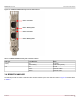
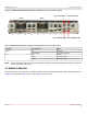
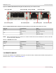
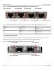
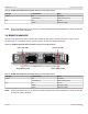
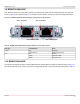
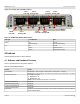
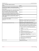
Table Of Contents
- Table of Contents
- 1 Regulatory and Safety Approvals
- 2 Functional Description
- 3 Network Link and Activity Indication
- 4 Features
- 4.1 Software and Hardware Features
- 4.2 Virtualization Features
- 4.3 VXLAN
- 4.4 NVGRE/GRE/IP-in-IP/Geneve
- 4.5 Stateless Offloads
- 4.6 Priority Flow Control
- 4.7 Virtualization Offload
- 4.8 SR-IOV
- 4.9 Network Partitioning (NPAR)
- 4.10 Security
- 4.11 RDMA over Converged Ethernet – RoCE
- 4.12 VMWare Enhanced Networking Stack (ENS)
- 4.13 Supported Combinations
- 4.14 Unsupported Combinations
- 5 Installing the Hardware
- 6 Software Packages and Installation
- 7 Updating the Firmware
- 8 Link Aggregation
- 9 System-Level Configuration
- 10 PXE Boot
- 11 SR-IOV – Configuration and Use Case Examples
- 12 NPAR – Configuration and Use Case Example
- 13 Tunneling Configuration Examples
- 14 RoCE – Configuration and Use Case Examples
- 15 DCBX – Data Center Bridging
- 16 DPDK – Configuration and Use Case Examples
- Revision History

Broadcom NetXtreme-E-UG304-2CS
22
NetXtreme-E User Guide User Guide for Dell Platforms
Figure 15: BCM957414M4140D Network Daughtercard (rNDC) Activity and Link LED Locations
NOTE: When a XTY28 transceiver is connected to a 25 Gb/s controller and if the link establishes at 1 Gb/s, the link LED
is off and the activity LED blinks.
3.5 BCM957412M4120D
This rNDC has SFP+ and RJ-45 ports, each with two LEDs to indicate traffic activities and link speed. The LEDs are shown
in Figure 16 and described Table 9 (Ports 1 and 2)/Table 10 (Ports 3 and 4).
Table 8: BCM957414M4140D Network Daughtercard (rNDC) Activity and Link LED Locations
LED Type Color/Behavior Notes
Activity Off No Activity
Green blinking Traffic Flowing Activity
Link Off No Link
Green Linked at 25 Gb/s
Yellow Linked at 10 Gb/s
Port 1 Link LED Port 2 Link LED
Port 1 Activity LED Port 2 Activity LED
Port 1 Port 2