
Users Guide
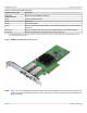
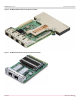

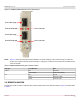
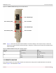
Table Of Contents
- Table of Contents
- 1 Regulatory and Safety Approvals
- 2 Functional Description
- 3 Network Link and Activity Indication
- 4 Features
- 4.1 Software and Hardware Features
- 4.2 Virtualization Features
- 4.3 VXLAN
- 4.4 NVGRE/GRE/IP-in-IP/Geneve
- 4.5 Stateless Offloads
- 4.6 Priority Flow Control
- 4.7 Virtualization Offload
- 4.8 SR-IOV
- 4.9 Network Partitioning (NPAR)
- 4.10 Security
- 4.11 RDMA over Converged Ethernet – RoCE
- 4.12 VMWare Enhanced Networking Stack (ENS)
- 4.13 Supported Combinations
- 4.14 Unsupported Combinations
- 5 Installing the Hardware
- 6 Software Packages and Installation
- 7 Updating the Firmware
- 8 Link Aggregation
- 9 System-Level Configuration
- 10 PXE Boot
- 11 SR-IOV – Configuration and Use Case Examples
- 12 NPAR – Configuration and Use Case Example
- 13 Tunneling Configuration Examples
- 14 RoCE – Configuration and Use Case Examples
- 15 DCBX – Data Center Bridging
- 16 DPDK – Configuration and Use Case Examples
- Revision History

Broadcom NetXtreme-E-UG304-2CS
18
NetXtreme-E User Guide User Guide for Dell Platforms
Figure 11: BCM957504-N425D OCP 3.0 SFF Card
3 Network Link and Activity Indication
Ethernet connections, the state of the network link, and activity are indicated by the LEDs on the rear connector as shown
in Table 4.
See the individual board data sheets for specific media design.
3.1 BCM957412AXXXX
The SFP+ port has two LEDs to indicate traffic activities and link speed. The LEDs are shown in Figure 12 and described in
Table 5.
Table 4: Network Link and Activity Indicated by Port LEDs
Port LED LED Appearance Network State
Link LED Off No link (cable disconnected)
Continuously illuminated Link
Activity LED Off No network activity
Blinking Network activity