
Users Guide

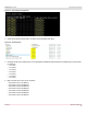
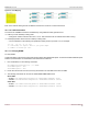
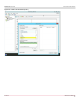
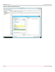
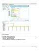
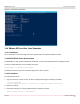
Table Of Contents
- Table of Contents
- 1 Regulatory and Safety Approvals
- 2 Functional Description
- 3 Network Link and Activity Indication
- 4 Features
- 4.1 Software and Hardware Features
- 4.2 Virtualization Features
- 4.3 VXLAN
- 4.4 NVGRE/GRE/IP-in-IP/Geneve
- 4.5 Stateless Offloads
- 4.6 Priority Flow Control
- 4.7 Virtualization Offload
- 4.8 SR-IOV
- 4.9 Network Partitioning (NPAR)
- 4.10 Security
- 4.11 RDMA over Converged Ethernet – RoCE
- 4.12 VMWare Enhanced Networking Stack (ENS)
- 4.13 Supported Combinations
- 4.14 Unsupported Combinations
- 5 Installing the Hardware
- 6 Software Packages and Installation
- 7 Updating the Firmware
- 8 Link Aggregation
- 9 System-Level Configuration
- 10 PXE Boot
- 11 SR-IOV – Configuration and Use Case Examples
- 12 NPAR – Configuration and Use Case Example
- 13 Tunneling Configuration Examples
- 14 RoCE – Configuration and Use Case Examples
- 15 DCBX – Data Center Bridging
- 16 DPDK – Configuration and Use Case Examples
- Revision History

Broadcom NetXtreme-E-UG304-2CS
124
NetXtreme-E User Guide User Guide for Dell Platforms
Figure 41: Server/Target Configuration
2. Create seven folders named Share1 to Share7 and individually share them.
Figure 42: Shared Folders
3. Configure the client by creating seven or more IP Address with different subnets that are accessible by the server system.
For example:
– 172.1.54.1
– 172.2.54.2
– 172.3.54.3
– 172.4.54.4
– 172.5.54.5
– 172.6.54.6
– 172.7.54.7
4. Map a network drive to the server as follows:
– Drive letter:\\172.1.55.1\Share1
– Drive letter:\\172.2.55.2\Share2
– Drive letter:\\172.3.55.3\Share3
– Drive letter:\\172.4.55.4\Share4
– Drive letter:\\172.5.55.5\Share5
– Drive letter:\\172.6.55.6\Share6
– Drive letter:\\172.7.55.7\Share7