
Users Guide
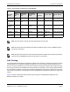
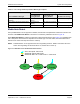
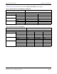
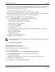

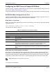
Table Of Contents
- Revision History
- Table of Contents
- Regulatory and Safety Approvals
- Functional Description
- Network Link and Activity Indication
- Features
- Software and Hardware Features
- Virtualization Features
- VXLAN
- NVGRE/GRE/IP-in-IP/Geneve
- Stateless Offloads
- UDP Fragmentation Offload
- Stateless Transport Tunnel Offload
- Multiqueue Support for OS
- SR-IOV Configuration Support Matrix
- SR-IOV
- Network Partitioning (NPAR)
- RDMA over Converged Ethernet – RoCE
- Supported Combinations
- Installing the Hardware
- Software Packages and Installation
- Windows Driver Advanced Properties and Event Log Messages
- Teaming
- System-level Configuration
- ISCSI Boot
- VXLAN: Configuration and Use Case Examples
- SR-IOV: Configuration and Use Case Examples
- NPAR – Configuration and Use Case Example
- RoCE – Configuration and Use Case Examples
- DCBX – Data Center Bridging
System-level ConfigurationNetXtreme-E User’s Manual
September 4, 2019 • NetXtreme-E-UG103 Page 51
Link Training
Link training allows both endpoints, the Broadcom adapter and the other side, to adjust power settings and other
tuning parameters to maximize the reliability and efficiency of the communication channel between the two
devices. The goal is to eliminate the need for channel-specific tuning between different cable lengths and types.
Link training is performed for CR/KR speeds and it precedes auto-negotiation. Link training is operational when
auto-negotiation is enabled. The link policy automatically disables link training if link training does not result in
a link up with the link partner. This link policy ensures compatibility with a link partner that does not support link
training.
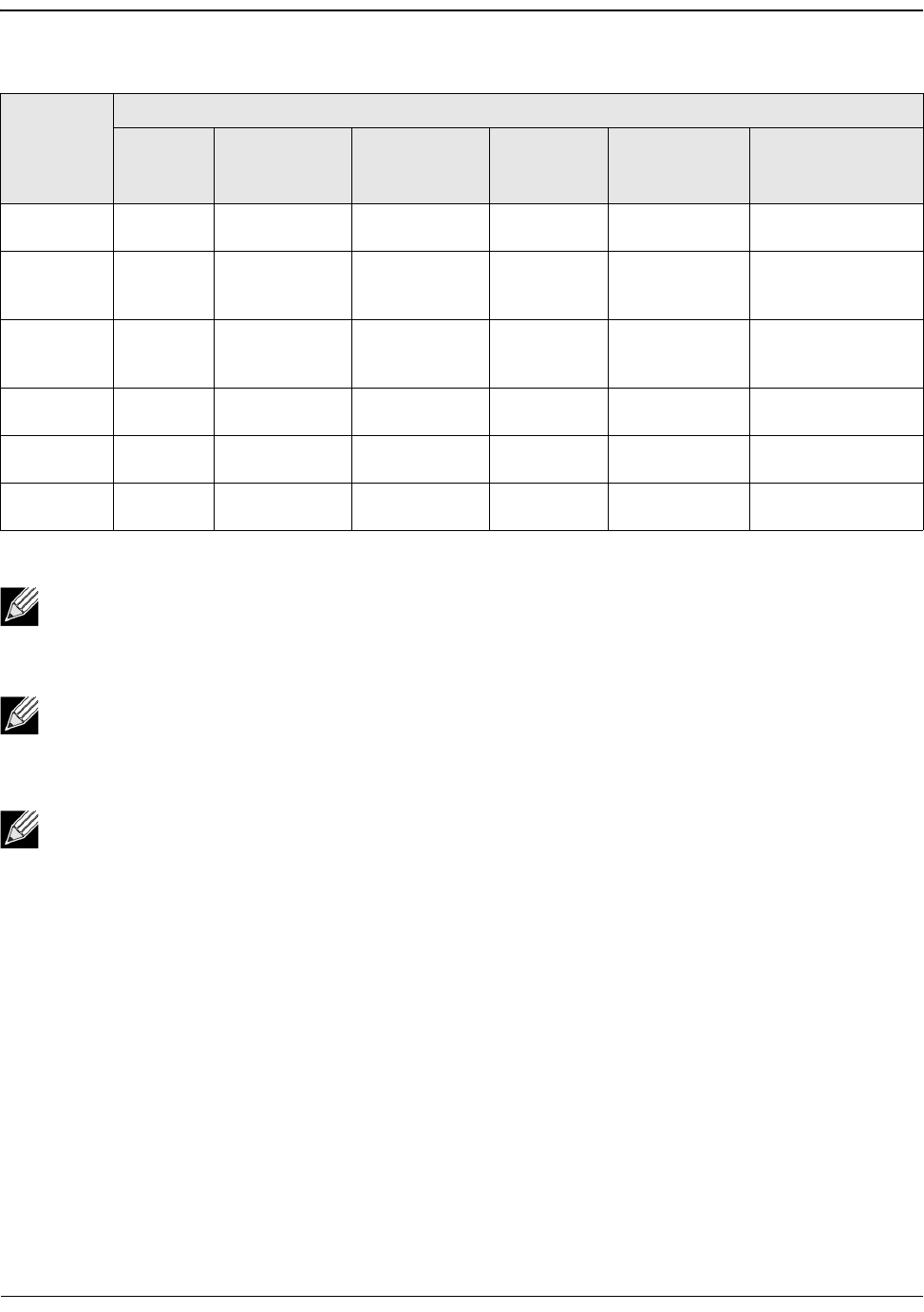
Tabl e 3 1 shows the relationship between media type and speed for the BCM5730X, BCM5740X, and
BCM5741X Ethernet controllers.
Table 30: Supported FEC Configurations for the BCM5741X
Local FEC
Setting
Link Partner FEC Setting
Force
Speed No
FEC
Force Speed
Base-R FEC
CL74
Force Speed
RS-FEC CL91/
CL108 AN (None)
An (None, Base-
R)
AN (None, Base-R,
RS)
Force No
FEC
Link w/no
FEC
No link No link No link No link No link
Force Speed
Base-R FEC
CL74
No link Base-R FEC
CL74
No link No link No link No link
Force RS-
FEC CL91/
CL108
No link No link RS-FEC CL91/
CL108
No link No link No link
AN (None) No link No link No link Link w/ no
FEC
Base-R FEC
CL74
RS-FEC CL91/CL108
AN (None,
Base-R)
No link No link No link Base-R FEC
CL74
Base-R FEC
CL74
RS-FEC CL91/CL108
AN (None,
Base-R, RS)
No link No link No link RS-FEC
CL91/CL108
RS-FEC CL91/
CL108
RS-FEC CL91/CL108
Note: For force speed, it must be the same speed setting on both sides.
Note: AN {None} means AN advertises the Base-R capable bit. Set the F0 bit on IEEE802.3by and
the F2 bit on Consortium.
Note: AN {None, Base-R} means the AN advertises the Base-R capable bit and requested bit. Set the
F0 and F1 bits on IEEE802.3by and the F2 and F4 bits on Consortium.